Adafruit LED Backpacks
|
|
|
- Jordan Simon
- 6 years ago
- Views:
Transcription

1 Adafruit LED Backpacks Created by lady ada Last updated on :40:11 PM UTC
2 Guide Contents Guide Contents Overview 1.2" 8x8 Matrix ( 8x8 Matrix Software 0.8" 8x8 Matrix Mini 8x8 Matrix Software 0.54" Alphanumeric Attaching the Backpack Attaching Header Prepare the header strip: Add the Backpack: Downloading the Arduino Library Wiring! Load Demo Library Reference ASCII data Writing Data 0.56" 7-Segment Backpack Seven-Segment Backpack Firmware 1.2" 7-segment Backpack Arduino Wiring - R3 and later Arduino Due and Other 3.3v Processors Arduino "Classic" Wiring Seven-Segment Backpack Firmware Bi-Color 8x8 Matrix Bi-Color 8x8 LED Backpack Firmware Schematic Bi-Color 24 Bargraph Attaching the bar-graph modules Soldering on breadboard pins Bi-Color Bargraph LED Backpack Wiring & Firmware Connecting Multiple Backpacks Adafruit Industries Page 2 of 88
3 Wire it Up Configure the Address Changing I2C Address Changing Addresses Changing the address in your code F.A.Q. Downloads Software Files HT16K33 8x16 LED Backpack Breakout 8x8 0.8" LED Backpack 8x8 1.2" LED Backpack 8x8 1.2" Bi-Color LED Backpack 16x8 1.2" LED Backpacks Quad 0.56" 7-Segment Quad 0.54" 14-segment Alphanumeric Quad 1.2" 7-Segment Bicolor 24-Bargraph Adafruit Industries Page 3 of 88
4 Overview What's better than a single LED? Lots of LEDs! A fun way to make a small display is to use an 8x8 matrix ( or a 4-digit 7-segment display ( Matrices like these are 'multiplexed' - so to control 64 LEDs you need 16 pins. That's a lot of pins, and there are driver chips like the MAX7219 ( that can control a matrix for you but there's a lot of wiring to set up and they take up a ton of space. Here at Adafruit we feel your pain! After all, wouldn't it be awesome if you could control a matrix without tons of wiring? That's where these adorable LED matrix backpacks come in. We have them in quite a few flavors! Adorable Mini 8x8 ( Classic 1.2" 8x8 (round and square dots) ( 4-digit 0.56" 7-segment ( 4-digit 1.2" 7-segment ( 4-digit 0.54" 14-segment Alphanumeric ( Bi-color 8x8 ( Bi-color Bargraph ( Adafruit Industries Page 4 of 88
5 Adafruit Industries Page 5 of 88
6 Adafruit Industries Page 6 of 88
7 The matrices use a driver chip that does all the heavy lifting for you: They have a built in clock so they multiplex the display. They use constant-current drivers for ultra-bright, consistant color (the images above are photographed at the dimmest setting to avoid overloading our camera!), 1/16 step display dimming, all via a simple I2C interface. The backpacks come with address-selection jumpers so you can connect up to four mini 8x8's or eight 7-segments (or a combination, such as four mini 8x8's and four 7-segments, etc) on a single I2C bus. The product kit comes with a fully tested and assembled LED backpack, a 4-pin header and the matrix of your choice. A bit of soldering is required to attach the matrix onto the backpack but its very easy to do and only takes about 5 minutes. Of course, in classic Adafruit fashion, we also have a detailed tutorial showing you how to solder, wire and control the display. We even wrote a very nice library for the backpacks so you can get running in under half an hour, displaying images on the matrix or numbers on the 7-segment. If you've been eyeing matrix displays but hesitated because of the complexity, his is the solution you've been looking for! Adafruit Industries Page 7 of 88

8 1.2" 8x8 Matrix This version of the LED backpack is designed for the 1.2" 8x8 matrices. They measure only 1.2"x1.2" so its a shame to use a massive array of chips to control it. This backpack solves the annoyance of using 16 pins or a bunch of chips by having an I2C constant-current matrix controller sit neatly on the back of the PCB. The controller chip takes care of everything, drawing all 64 LEDs in the background. All you have to do is write data to it using the 2-pin I2C interface. There are two address select pins so you can select one of 8 addresses to control up to 8 of these on a single 2-pin I2C bus (as well as whatever other I2C chips or sensors you like). The driver chip can 'dim' the entire display from 1/16 brightness up to full brightness in 1/16th steps. It cannot dim individual LEDs, only the entire display at once. These instruction apply to the 1.2" Matrix only! If you have a Bi-Color or 0.8" square matrix, follow the links on the left side of the page. When you buy a pack from Adafruit, it comes with the fully tested and assembled backpack as well as a 8x8 matrix in one of the colors we provide (say, red, yellow or green). You'll need to solder the matrix onto the backpack but its an easy task. WATCH OUT! THE MATRIX Adafruit Industries Page 8 of 88


9 MUST BE INSTALLED THE RIGHT WAY! First look for the line of text on the side of the LED matrix WATCH OUT! THE MATRIX MUST BE INSTALLED THE RIGHT WAY! Find the corner of the backpack with a filled in dot. Make sure that the text on the side of the matrix is on the same side as the filled dot WATCH OUT! THE MATRIX MUST BE INSTALLED THE RIGHT WAY! Slide the matrix into the backpack and flip it over. Triple check that the text is on the same side as the From Adafruit text Adafruit Industries Page 9 of 88


10 Solder in all 16 pins Then clip the matrix leads short Adafruit Industries Page 10 of 88

11 Now you're ready to wire it up to a microcontroller. We'll assume you want to use a 4pin header. You can also of course solder wires directly. Place a 4-pin piece of header with the LONG pins down into the breadboard. Adafruit Industries Page 11 of 88
mini 8x8 Matrix Software We wrote a basic library to help you work with the mini 8x8 matrix backpack.")
12 Place the soldered backpack on top of the header. Solder the four pins That's it! now you're ready to run the firmware! ( 8x8 Matrix Software We wrote a basic library to help you work with the mini 8x8 matrix backpack. The library is written for the Arduino and will work with any Arduino as it just uses the I2C pins. The code is very portable and can be easily adapted to any I2C-capable micro. Wiring to the matrix is really easy Connect CLK to the I2C clock - on Arduino UNO thats Analog #5, on the Leonardo its Digital #3, on the Mega its digital #21 Connect DAT to the I2C data - on Arduino UNO thats Analog #4, on the Leonardo its Digital #2, on the Mega its digital #20 Connect GND to common ground Connect VCC+ to power - 5V is best but 3V also seems to work for 3V microcontrollers. Next, download the Adafruit LED Backpack library from github ( To download click the DOWNLOADS button in the top right corner, rename the uncompressed folder Adafruit_LEDBackpack. Check that the Adafruit_LEDBackpack folder contains Adafruit_LEDBackpack.cpp and Adafruit_LEDBackpack.h Place the Adafruit_LEDBackpack library folder your arduinosketchfolder/libraries/ folder. You may need to create the libraries subfolder if its your first library. You'll also need to download the Adafruit GFX library ( that provides the graphics drawing routines. Restart the IDE. Adafruit Industries Page 12 of 88

13 Once you've restarted you should be able to select thefile->examples- >Adafruit_LEDBackpack->matrix88 example sketch. Upload it to your Arduino as usual. You should see a basic test program that goes through a bunch of different drawing routine Once you're happy that the matrix works, you can write your own sketches. The 8x8 matrix supports everything the Adafruit GFX library - drawing pixels, lines, rectancles, circles, triangles, roundrects, and small bitmaps. For more details check out the GFX page which will detail all of the GFX routines ( All the drawing routines only change the display memory kept by the Arduino. Don't forget to call writedisplay() after drawing to 'save' the memory out to the matrix via I2C. There are also a few small routines that are special to the matrix: setbrightness(brighness)- will let you change the overall brightness of the entire display. 0 is least bright, 15 is brightest and is what is initialized by the display when you start. You can call this function at any time to change the brightness of the - entire- display Adafruit Industries Page 13 of 88
 at the top-left when the")
14 blinkrate(rate) - You can blink the entire display. 0 is no blinking. 1, 2 or 3 is for display blinking.you can call this function at any time to change the blink rate of the - entire- display The default orientation for graphics commands on this display places pixel (0,0) at the top-left when the header is at the left and Adafruit logo at the right. To use the matrix as shown above (header at top, logo at bottom), call matrix.setrotation(3) before issuing graphics commands. Adafruit Industries Page 14 of 88

15 0.8" 8x8 Matrix This version of the LED backpack is designed for these very cute miniature 8x8 matrices. They measure only 0.8"x0.8" so its a shame to use a massive array of chips to control it. This backpack solves the annoyance of using 16 pins or a bunch of chips by having an I2C constant-current matrix controller sit neatly on the back of the PCB. The controller chip takes care of everything, drawing all 64 LEDs in the background. All you have to do is write data to it using the 2-pin I2C interface. There are two address select pins so you can select one of 4 addresses to control up to 4 of these on a single 2-pin I2C bus (as well as whatever other I2C chips or sensors you like). The driver chip can 'dim' the entire display from 1/16 brightness up to full brightness in 1/16th steps. It cannot dim individual LEDs, only the entire display at once. These instruction apply to the 0.8" Matrix only! If you have a Bi-Color or 1.2" square matrix, follow the links on the left side of the page. When you buy a pack from Adafruit, it comes with the fully tested and assembled backpack as well as a 8x8 matrix in one of the colors we provide (say, red, yellow or green). You'll need to solder the matrix onto the backpack but its an easy task. Remove the parts from packaging and place the LED Adafruit Industries Page 15 of 88


16 matrix OVER the silkscreen side. It can go 'either way' - the matrix is symmetric so as long as it goes onto the front it will work in any orientation. Do not solder the matrix over the chip on the back of the backpack - it will not work then! Turn the backpack over so its sitting flat on the matrix. Solder all 16 pins. Adafruit Industries Page 16 of 88

17 Clip the long pins. Now you're ready to wire it up to a microcontroller. We'll assume Adafruit Industries Page 17 of 88


18 you want to use a 4pin header. You can also of course solder wires directly. Place a 4-pin piece of header with the LONG pins down into the breadboard. Place the soldered backpack on top of the header. Solder 'em! Adafruit Industries Page 18 of 88
19 That's it! now you're ready to run the firmware! Mini 8x8 Matrix Software We wrote a basic library to help you work with the mini 8x8 matrix backpack. The library is written for the Arduino and will work with any Arduino as it just uses the I2C pins. The code is very portable and can be easily adapted to any I2C-capable micro. Wiring to the matrix is really easy Connect CLK to the I2C clock - on Arduino UNO thats Analog #5, on the Leonardo its Digital #3, on the Mega its digital #21 Connect DAT to the I2C data - on Arduino UNO thats Analog #4, on the Leonardo its Digital #2, on the Mega its digital #20 Connect GND to common ground Connect VCC+ to power - 5V is best but 3V also seems to work for 3V microcontrollers. Next, download the Adafruit LED Backpack library from github ( To download click the DOWNLOADS button in the top right corner, rename the uncompressed folder Adafruit_LEDBackpack. Check that the Adafruit_LEDBackpack folder contains Adafruit_LEDBackpack.cpp and Adafruit_LEDBackpack.h Place the Adafruit_LEDBackpack library folder your arduinosketchfolder/libraries/ folder. You may need to create the libraries subfolder if its your first library. You'll also need to download the Adafruit GFX library ( that provides the graphics drawing routines. Follow the same instructions as above, but with Adafruit_GFX instead of Adafruit_LEDBackpack. Restart the IDE. Once you've restarted you should be able to select thefile->examples- >Adafruit_LEDBackpack->matrix88 example sketch. Upload it to your Arduino as usual. You should see a basic test program that goes through a bunch of different drawing routines Adafruit Industries Page 19 of 88
20 Once you're happy that the matrix works, you can write your own sketches. The 8x8 matrix supports everything the Adafruit GFX library - drawing pixels, lines, rectancles, circles, triangles, roundrects, and small bitmaps. For more details check out the GFX page which will detail all of the GFX routines ( All the drawing routines only change the display memory kept by the Arduino. Don't forget to call writedisplay() after drawing to 'save' the memory out to the matrix via I2C. There are also a few small routines that are special to the matrix: setbrightness(brighness)- will let you change the overall brightness of the entire display. 0 is least bright, 15 is brightest and is what is initialized by the display when you start blinkrate(rate) - You can blink the entire display. 0 is no blinking. 1, 2 or 3 is for display blinking. Adafruit Industries Page 20 of 88
 can be used to use the display in other orientations. Adafruit Industries https://learn.adafruit.com/adafruit-led-backpack Page 21 of 88")
21 The default orientation for graphics commands on this display places pixel (0,0) at the top-left when the header is at the top and Adafruit logo at the bottom. matrix.setrotation() can be used to use the display in other orientations. Adafruit Industries Page 21 of 88
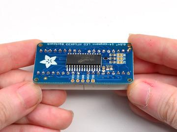
22 0.54" Alphanumeric ( This version of the LED backpack is designed for two dual 14-segment "Alphanumeric" displays. These 14-segment displays normally require 18 pins (4 'characters' and 14 total segments each) This backpack solves the annoyance of using 18 pins or a bunch of chips by having an I2C constant-current matrix controller sit neatly on the back of the PCB. The controller chip takes care of everything, drawing all the LEDs in the background. All you have to do is write data to it using the 2-pin I2C interface. There are three address select pins so you can select one of 8 addresses to control up to 8 of these on a single 2-pin I2C bus (as well as whatever other I2C chips or sensors you like). The driver chip can 'dim' the entire display from 1/16 brightness up to full brightness in 1/16th steps. It cannot dim individual LEDs, only the entire display at once. Attaching the Backpack When you buy a pack from Adafruit, it comes with the fully tested and assembled backpack as well as two dual 14-segment display in one of the colors we provide (say, red, yellow, blue or green). You'll need to solder the matrix onto the backpack but it's an easy task. Remove the parts from Adafruit Industries Page 22 of 88

23 packaging and place the LED matrices OVER the silkscreen side. DO NOT PUT THE DISPLAY ON UPSIDE DOWN OR IT WONT WORK!! Check the image below to make sure the 'decimal point' dots are on the bottom, matching the silkscreen. Turn the backpack over so it is sitting flat on the matrix. Adafruit Industries Page 23 of 88


24 Solder all of the pins! Adafruit Industries Page 24 of 88
25 Adafruit Industries Page 25 of 88


26 Clip the long pins. Adafruit Industries Page 26 of 88

27 Check your work, making sure each pin is nicely soldered, and there's no cold solder joints or shorted pins Attaching Header Prepare the header strip: Cut the strip to length if necessary. It will be easier to solder if you insert it into a breadboard - long pins down Adafruit Industries Page 27 of 88

.")
28 Add the Backpack: Place the backpack board over the pins so that the short pins poke through the breakout pads Solder all 5 pins! That's it! now you're ready to run the firmware on your Arduino! Downloading the Arduino Library We wrote a basic library to help you work with the alphanumeric backpack. The library is written for the Arduino and will work with any Arduino as it just uses the I2C pins. The code is very portable and can be easily adapted to any I2C-capable micro. Begin by downloading our Adafruit LED Backpack library from github ( You can do that by visiting the github repo and manually downloading or, easier, just click Adafruit Industries Page 28 of 88
29 this button to download the zip Download LED Backpack Library Rename the uncompressed folder Adafruit_LEDBackpack and check that the Adafruit_LEDBackpack folder contains Adafruit_LEDBackpack.cpp and Adafruit_LEDBackpack.h Place the Adafruit_LEDBackpack library folder your arduinosketchfolder/libraries/ folder. You may need to create the libraries subfolder if its your first library. Restart the IDE. We also have a great tutorial on Arduino library installation at: ( You'll also need to download the Adafruit GFX library - even though this particular backpack doesn't use it! Its just one of those Arduino dependencies! You can grab the Adafruit GFX library from github ( or download by clicking below. Download Adafruit GFX Library Rename the uncompressed folder Adafruit_GFX and check that the Adafruit_GFX folder contains Adafruit_GFX.cpp and Adafruit_GFX.h Place the Adafruit_GFX library folder your arduinosketchfolder/libraries/ folder like you did with the LED backpacks Wiring! Nex up, let's wire it up to an Arduino. We'll be using an Arduino. Connect CLK to the I2C clock - on Arduino UNO thats Analog #5, on the Leonardo it's Digital #3, on the Mega it's digital #21 Connect DAT to the I2C data - on Arduino UNO thats Analog #4, on the Leonardo it's Digital #2, on the Mega it's digital #20 Connect GND to common ground Connect VCC+ to power - 5V is best but 3V will work if that's all you've got (it will be dimmer) Connect Vi2c to your microcontroller's logic level (3-5V) - If you're using an Arduino, this is almost certainly 5V. If its a 3V Arduino such as a Due, connect it to 3V Both Vi2c and Vcc MUST be connected to 3 to 5VDC! Vcc is for the LED driver power, Vi2c is what sets the logic level for communication to the chip. Adafruit Industries Page 29 of 88
30 Load Demo Restart the Arduino IDE and load up the File->Adafruit_LEDBackpack->quadalphanum demo Adafruit Industries Page 30 of 88

31 Upload to your Arduino, and open up the Serial console at 9600 baud speed. You'll see each digit light up all the segments, then the display will scroll through the 'font table' showing every character that it knows how to display. Finally, you'll get a notice to start typing into the serial console. Type a message and hit return, you'll see it scroll onto the display! Adafruit Industries Page 31 of 88

32 Library Reference For the quad displays, we have a special object that can handle ascii data for easy printing. Adafruit Industries Page 32 of 88

33 You can create the object with Adafruit_AlphaNum4 alpha4 = Adafruit_AlphaNum4(); There's no arguments or pins because the backpacks use the fixed I2C pins. By default, the address is 0x70, but you can pass in the I2C address used when you initialize the display with begin alpha4.begin(0x70); // pass in the address Next up, the segments can be turned on/off for each digit by writing the 'raw' bitmap you want, for example, all the LEDs off on digit #3 is alpha4.writedigitraw(3, 0x0); All the segments on for digit #0 is alpha4.writedigitraw(0, 0x3FFF); This is the segment map: the 16 bit digit you pass in for raw image has this mapping: 0 DP N M L K J H G2 G1 F E D C B A The first bit isn't used, you can make it 0 or 1 To turn on just the A segment, use 0x0001 To turn on just the G1 segment, use 0x0040 ASCII data Adafruit Industries Page 33 of 88
34 If you're just looking to print 'text' you can use our font table, just pass in an ASCII character! For example, to set digit #0 to A call: alpha4.writedigitascii(0, 'A') Writing Data Don't forget to 'write' the data to the display with alpha4.writedisplay(); That's what actually 'sets' the data onto the LEDs! Adafruit Industries Page 34 of 88
 This backpack solves the annoyance of using 13 pins or a bunch of chips by having an I2C constant-current")
35 0.56" 7-Segment Backpack This version of the LED backpack is designed for these big bright 7-segment displays. These 7-segment displays normally require 13 pins (5 'characters' and 8 total segments each) This backpack solves the annoyance of using 13 pins or a bunch of chips by having an I2C constant-current matrix controller sit neatly on the back of the PCB. The controller chip takes care of everything, drawing all the LEDs in the background. All you have to do is write data to it using the 2-pin I2C interface. There are three address select pins so you can select one of 8 addresses to control up to 8 of these on a single 2-pin I2C bus (as well as whatever other I2C chips or sensors you like). The driver chip can 'dim' the entire display from 1/16 brightness up to full brightness in 1/16th steps. It cannot dim individual LEDs, only the entire display at once. When you buy a pack from Adafruit, it comes with the fully tested and assembled backpack as well as a 7-segment display in one of the colors we provide (say, red, yellow, blue or green). You'll need to solder the matrix onto the backpack but it's an easy task. Remove the parts from packaging and place the LED matrix OVER the silkscreen Adafruit Industries Page 35 of 88

36 side. DO NOT PUT THE DISPLAY ON UPSIDE DOWN OR IT WONT WORK!! Check the image below to make sure the 'decimal point' dots are on the bottom, matching the silkscreen. Turn the backpack over so it is sitting flat on the matrix. Solder all 14 pins. Adafruit Industries Page 36 of 88


37 Clip the long pins. Adafruit Industries Page 37 of 88

38 Now you're ready to wire it up to a microcontroller. We'll assume you want to use a 4pin header. You can also of course solder wires directly. Place a 4-pin piece of header with the LONG pins down into the breadboard. Place the soldered backpack on top of the header and Solder 'em! That's it! now you're ready to run the firmware! Seven-Segment Backpack Firmware We wrote a basic library to help you work with the 7-segment backpack. The library is written for the Arduino and will work with any Arduino as it just uses the I2C pins. The code is very portable and can be easily adapted to any I2C-capable micro. Wiring to the matrix is really easy Adafruit Industries Page 38 of 88
39 Connect CLK to the I2C clock - on Arduino UNO thats Analog #5, on the Leonardo it's Digital #3, on the Mega it's digital #21 Connect DAT to the I2C data - on Arduino UNO thats Analog #4, on the Leonardo it's Digital #2, on the Mega it's digital #20 Connect GND to common ground Connect VCC+ to power - 5V is best but 3V also seems to work for 3V microcontrollers. Next, download the Adafruit LED Backpack library from github ( To download click the DOWNLOADS button in the top right corner, rename the uncompressed folder Adafruit_LEDBackpack. Check that the Adafruit_LEDBackpack folder contains Adafruit_LEDBackpack.cpp and Adafruit_LEDBackpack.h Place the Adafruit_LEDBackpack library folder your arduinosketchfolder/libraries/ folder. You may need to create the libraries subfolder if it's your first library. You'll also need to download the Adafruit GFX library ( - rename it Adafruit_GFX and install it as the LED backpack library. It's not actually used for the 7-segment, it's only for the matrix backpacks but it's still required. Restart the IDE. Once you've restarted you should be able to select thefile?examples? Adafruit_LEDBackpack?sevenseg example sketch. Upload it to your Arduino as usual. You should see a basic test program that goes through a bunch of different routines. Adafruit Industries Page 39 of 88
40 Once you're happy that the matrix works, you can write your own sketches. There's a few ways you can draw to the display. The easiest is to just call print - just like you do with Serial print(variable,hex) - this will print a hexidecimal number, from 0000 up to FFFF print(variable,dec) or print(variable) - this will print a decimal integer, from 0000 up to 9999 If you need more control, you can call writedigitnum(location, number) - this will write the number (0-9) to a single location. Location #0 is all the way to the left, location #2 is the colon dots so you probably want to skip it, location #4 is all the way to the right. If you want a decimal point, call writedigitnum(location, number, true) which will paint the decimal point. To draw the colon, usedrawcolon(true or false) If you want even more control, you can call writedigitraw(location,bitmask) to draw a raw 8-bit mask (as stored in a uint8_t) to that location. All the drawing routines only change the display memory kept by the Arduino. Don't forget Adafruit Industries Page 40 of 88
41 to call writedisplay() after drawing to 'save' the memory out to the matrix via I2C. There are also a few small routines that are special to the backpack: setbrightness(brightness)- will let you change the overall brightness of the entire display. 0 is least bright, 15 is brightest and is what is initialized by the display when you start blinkrate(rate) - You can blink the entire display. 0 is no blinking. 1, 2 or 3 is for display blinking. Adafruit Industries Page 41 of 88

42 1.2" 7-segment Backpack These backpacks drive the massive 1.2" 7-segment modules. With 2 leds per segment these make a gorgeous and impressive display. The 7-segment displays normally require 16 pins to drive. This backpack uses an I2C constant-current matrix controller on the back of the PCB, so you only need 2 pins to drive it! The controller chip takes care of multiplexing all the LEDs in the background. All you have to do is write data to it using the 2-pin I2C interface. There are three address select pins so you can select one of 8 addresses to control up to 8 of these on a single 2-pin I2C bus (as well as whatever other I2C chips or sensors you like). The driver chip can 'dim' the entire display from 1/16 brightness up to full brightness in 1/16th steps. It cannot dim individual LEDs, only the entire display at once. When you buy a pack from Adafruit, it comes with the fully tested and assembled backpack as well as a 7-segment display in one of the colors we provide (say, red, yellow, blue or green). You'll need to solder the matrix onto the backpack but its an easy task. Remove the parts from packaging and place the LED matrix OVER the silkscreen side. DO NOT PUT THE DISPLAY ON UPSIDE DOWN OR IT WONT WORK!! Check the image below to make sure the 'decimal point' dots are in the same location as the ones on the silkscreen. Adafruit Industries Page 42 of 88

43 Turn the backpack over so its sitting flat on the matrix and ready to solder. Adafruit Industries Page 43 of 88


44 Then solder each pin. There are 8 on each end for a total of 16. That completes the basic assembly. For use on a breadboard, you will want to also install a 5-pin header on the edge of the board. Adafruit Industries Page 44 of 88


45 Clip the long pins close to the board. Cut the header strip to length if necessary and insert LONG pins down into the breadboard. Adafruit Industries Page 45 of 88
 \"-\" - GND \"IO\" - I2C bus voltage. Due to the size of this display, there are 2 LEDs in series for each segment. Because of this, the display requires 5v to run.")
 Adafruit Industries https://learn.")
46 Then solder all 5 pins. Now you are ready to wire it to your microcontroller. The required connections are: "D" - I2C Data Pin (SDA) "C" - I2C Clock Pin (SCL) "+" - 5v. (Will not run on 3.3v!) "-" - GND "IO" - I2C bus voltage. Due to the size of this display, there are 2 LEDs in series for each segment. Because of this, the display requires 5v to run. It will not run on 3.3v. For use with 3.3v processors, connect the IO pin to 3.3v. This will keep the I2C bus signals at a safe level for your processor. With 5v processors like the Arduino UNO, this pin can be connected to either 5v or 3.3v. (use 3.3v if there will be other 3.3v devices on the bus) Adafruit Industries Page 46 of 88

47 Arduino Wiring - R3 and later Connect: D -> SDA C -> SCL + -> 5v - -> GND IO -> jumper to + for 5v. Arduino Due and Other 3.3v Processors Connect: D -> SDA C -> SCL + -> 5v - -> GND IO -> 3.3v Arduino "Classic" Wiring Connect: D -> Analog-4 or Digital 20 for the Mega C -> Analog-5 or Digital 21 for the Mega + -> 5v - -> GND IO -> jumper to + for 5v. Adafruit Industries Page 47 of 88
48 OK, now on to the firmware! Seven-Segment Backpack Firmware Our 7-segment backpack library makes it easy to program these displays. The library is written for the Arduino and will work with any Arduino as it just uses the I2C pins. The code is very portable and can be easily adapted to any I2C-capable micro. You can download the Adafruit LED Backpack library from github ( To download click the DOWNLOADS button in the top right corner, rename the uncompressed folder Adafruit_LEDBackpack. Check that the Adafruit_LEDBackpack folder contains Adafruit_LEDBackpack.cpp and Adafruit_LEDBackpack.h. If you need help with installing you libraries, we have a detailed guide here: Installing Arduino Libraries You'll also need to download the Adafruit GFX library ( - rename it Adafruit_GFX and install it as the LED backpack library. Close all open IDE windows and restart the IDE. Once you've restarted you should be able to select thefile?examples? Adafruit_LEDBackpack?sevenseg example sketch. Upload it to your Arduino as usual. You should see a "sevenseg" example sketch that will demonstrate various capabilities of the library and the display. Adafruit Industries Page 48 of 88
 - this will print a hexidecimal number, from 0000 up to FFFF print(variable,dec) or print(variable) - this will")
49 Once you're happy that the matrix works, you can write your own sketches. There's a few ways you can draw to the display. The easiest is to just call print - just like you do with Serial print(variable,hex) - this will print a hexidecimal number, from 0000 up to FFFF print(variable,dec) or print(variable) - this will print a decimal integer, from 0000 up to 9999 If you need more control, you can call writedigitnum(location, number) - this will write the number (0-9) to a single location. Location #0 is all the way to the left, location #2 is the colon dots so you probably want to skip it, location #4 is all the way to the right. To control the colon and decimal points, use the writedigitraw(location, bitmap) function. (Note that both dots of the center colon are wired together internal to the display, so it is not possible to address them separately.) Specify 2 for the location and the bits are mapped as follows: 0x02 - center colon (both dots) 0x04 - left colon - lower dot 0x08 - left colon - upper dot 0x10 - decimal point Adafruit Industries Page 49 of 88
50 If you want a decimal point, call writedigitnum(location, number, true) which will paint the decimal point. To draw the colon, use drawcolon(true or false) If you want full control of the segments in all digits, you can call writedigitraw(location,bitmask) to draw a raw 8-bit mask (as stored in a uint8_t) to anylocation. All the drawing routines only change the display memory kept by the Arduino. Don't forget to call writedisplay() after drawing to 'save' the memory out to the matrix via I2C. There are also a few small routines that are special to the backpack: setbrightness(brighness)- will let you change the overall brightness of the entire display. 0 is least bright, 15 is brightest and is what is initialized by the display when you start blinkrate(rate) - You can blink the entire display. 0 is no blinking. 1, 2 or 3 is for display blinking. Adafruit Industries Page 50 of 88
51 Bi-Color 8x8 Matrix This version of the LED backpack is designed for these bright and colorful square=pixeled 8x8 matrices. They have 64 red and 64 green LEDs inside, for a total of 128 LEDs controlled as a 8x16 matrix. This backpack solves the annoyance of using 24 pins or a bunch of chips by having an I2C constant-current matrix controller sit neatly on the back of the PCB. The controller chip takes care of everything, drawing all 128 LEDs in the background. All you have to do is write data to it using the 2-pin I2C interface. There are three address select pins so you can select one of 8 addresses to control up to 8 of these on a single 2-pin I2C bus (as well as whatever other I2C chips or sensors you like). The driver chip can 'dim' the entire display from 1/16 brightness up to full brightness in 1/16th steps. It cannot dim individual LEDs, only the entire display at once. Pay close attention to the instructions for positioning the matrix. It must be oriented correctly to work and is almost impossible to remove it once it has been soldered to the backpack! Adafruit Industries Page 51 of 88

52 When you buy a pack from Adafruit, it comes with the fully tested and assembled backpack as well as a 8x8 matrix. You'll need to solder the matrix onto the backpack but its an easy task. Remove the parts from packaging and place the LED matrix OVER the silkscreen side. The matrix must be soldered on the correct orientation or it will not work! Check for the side of the matrix that has printing on it. Then look for the front of the PCB that has a circle instead of a square in the corner and line those up as shown on the left Do not solder the matrix over the chip on the back of the backpack - it will not work then! Adafruit Industries Page 52 of 88

53 Turn the backpack over so its sitting flat on the matrix. Solder all 24 pins. Adafruit Industries Page 53 of 88

54 Clip the long pins Now you're ready to wire it up to a microcontroller. We'll assume Adafruit Industries Page 54 of 88


55 you want to use a 4pin header. You can also of course solder wires directly. Place a 4-pin piece of header with the LONG pins down into the breadboard. Place the soldered backpack on top of the header. Solder 'em! Adafruit Industries Page 55 of 88
56 Bi-Color 8x8 LED Backpack Firmware We wrote a basic library to help you work with the bi-color 8x8 matrix backpack. The library is written for the Arduino and will work with any Arduino as it just uses the I2C pins. The code is very portable and can be easily adapted to any I2C-capable micro. Wiring to the matrix is really easy Connect CLK to the I2C clock - on Arduino UNO thats Analog #5, on the Leonardo its Digital #3, on the Mega its digital #21 Connect DAT to the I2C data - on Arduino UNO thats Analog #4, on the Leonardo its Digital #2, on the Mega its digital #20 Connect GND to common ground Connect VCC+ to power - 5V is best but 3V also seems to work for 3V microcontrollers. Next, download the Adafruit LED Backpack library from github ( To download click the DOWNLOADS button in the top right corner, rename the uncompressed folder Adafruit_LEDBackpack. Check that the Adafruit_LEDBackpack folder contains Adafruit_LEDBackpack.cpp and Adafruit_LEDBackpack.h Place the Adafruit_LEDBackpack library folder your arduinosketchfolder/libraries/ folder. You may need to create the libraries subfolder if its your first library. You'll also need to download the Adafruit GFX library ( that provides the graphics drawing routines. Restart the IDE. Once you've restarted you should be able to select thefile->examples- >Adafruit_LEDBackpack->bicolor88 example sketch. Upload it to your Arduino as usual. You should see a basic test program that goes through a bunch of different drawing routines Adafruit Industries Page 56 of 88
57 Once you're happy that the matrix works, you can write your own sketches. The 8x8 matrix supports everything the Adafruit GFX library - drawing pixels, lines, rectangles, circles, triangles, roundrects, and small bitmaps. For more details check out the GFX page which will detail all of the GFX routines ( All the drawing routines only change the display memory kept by the Arduino. Don't forget to call writedisplay() after drawing to 'save' the memory out to the matrix via I2C. There are also a few small routines that are special to the matrix: setbrightness(brightness)- will let you change the overall brightness of the entire display. 0 is least bright, 15 is brightest and is what is initialized by the display when you start blinkrate(rate) - You can blink the entire display. 0 is no blinking. 1, 2 or 3 is for display blinking. Adafruit Industries Page 57 of 88
, call matrix.setrotation(3) before issuing graphics commands. Schematic Adafruit Industries https://learn.adafruit.")
58 The default orientation for graphics commands on this display places pixel (0,0) at the top-left when the header is at the left and Adafruit logo at the right. To use the matrix as shown above (header at top, logo at bottom), call matrix.setrotation(3) before issuing graphics commands. Schematic Adafruit Industries Page 58 of 88
.")
59 Bi-Color 24 Bargraph This version of the LED backpack is designed for these bright and colorful bi-color bargraph modules. Each module has 12 red and 12 green LEDs inside, for a total of 24 LEDs controlled as a 1x12 matrix. We put two modules on each backpack for a 24-bar long bargraph (48 total LEDs). This backpack solves the annoyance of using lots of pins or a bunch of chips by having an I2C constant-current matrix controller sit neatly on the back of the PCB. The controller chip takes care of everything, drawing all 48 LEDs in the background. All you have to do is write data to it using the 2-pin I2C interface. There are three address select pins so you can select one of 8 addresses to control up to 8 of these on a single 2-pin I2C bus (as well as whatever other I2C chips or sensors you like). The driver chip can 'dim' the entire display from 1/16 brightness up to full brightness in 1/16th steps. It cannot dim individual LEDs, only the entire display at once. Adafruit Industries Page 59 of 88


60 Attaching the bar-graph modules Pay close attention to the instructions for positioning the bargraphs. They must be oriented correctly to work and is almost impossible to remove them once soldered to the backpack! Remove the parts from packaging and place the LED bargraphs over the outlines on the top of the PCB. The bargraph must be soldered on the correct orientation or it will not work! Check for the side of the bargraph that has printing on it. Then look for the outline on the PCB that has "Text on this side" marked! Do not solder the matrix onto the back of the PCB, it won't work either! Adafruit Industries Page 60 of 88


61 To keep the two bargraphs lined up nicely, you can use a little masking or scotch tape on the bargraph modules, tape them so they are in a straight line. There is a little play during soldering so if you don't do this the two modules may not be in a perfect line. Turn over the PCB and bend opposite-corner pins of the modules out so that the modules are fixed in place against the PCB. Now is a good time to do a last check that you oriented the modules the right way! Adafruit Industries Page 61 of 88


62 Solder all the module pins in! Adafruit Industries Page 62 of 88

63 OK nice work! Once soldered, clip each pin. They're quite short and the pins are thicker than usual, so do this over/inside a trash bin so that the pins don't fly off and it you or your pets. Adafruit Industries Page 63 of 88


64 Everything should be neat and clipped, you're done! Soldering on breadboard pins This is an optional step - you only need to do this step if you're planning on using the bargraph in a breadboard. Chances are you may want to solder wires directly to the pads instead, so you can mount the bargraph elsewhere. Anyhow, skip this step if its not for you! Break off a piece of male header, 4 pins long. Plug the long ends into a solderless breadboard. Adafruit Industries Page 64 of 88


65 Place the PCB on top. you may need to support it a little since its quite long. Solder these 4 pins too, since you're good at it now this should be easy. Adafruit Industries Page 65 of 88

66 Bi-Color Bargraph LED Backpack Wiring & Firmware We wrote a basic library to help you work with the bi-color bargraph backpack. The library is written for the Arduino and will work with any Arduino as it just uses the I2C pins. The code is very portable and can be easily adapted to any I2C-capable micro. Wiring to the bargraph is really easy Connect SCL to the I2C clock - on Arduino UNO thats Analog #5, on the Leonardo its Digital #3, on the Mega its digital #21 Connect SDA to the I2C data - on Arduino UNO thats Analog #4, on the Leonardo its Digital #2, on the Mega its digital #20 Connect GND to common ground Connect VCC to power - 5V is best but 3V also seems to work for 3V microcontrollers. Adafruit Industries Page 66 of 88

67 Next, download the Adafruit LED Backpack library from github ( To download click the DOWNLOADS button in the top right corner, rename the uncompressed folder Adafruit_LEDBackpack. Check that the Adafruit_LEDBackpack folder contains Adafruit_LEDBackpack.cpp and Adafruit_LEDBackpack.h Place the Adafruit_LEDBackpack library folder your arduinosketchfolder/libraries/ folder. You may need to create the libraries subfolder if its your first library. You'll also need to download the Adafruit GFX library ( that provides the graphics drawing routines. Restart the IDE. Once you've restarted you should be able to select thefile->examples- >Adafruit_LEDBackpack->bargraph24 example sketch. Upload it to your Arduino as usual. You should see a basic test program that tests all the LEDs with different colors Using the library interface is very easy. Start by creating the object with Adafruit_24bargraph bar = Adafruit_24bargraph(); you can name it whatever you want, not just bar Adafruit Industries Page 67 of 88
68 Then initialize it with bar.begin(0x70); // pass in the address You can init with any address from 0x70 to 0x77, just make sure you solder in the matching solder jumpers! Finally, write to the bargraph with bar.setbar(lednumber, ledcolor); Where lednumber is 0 thru 23. ledcolor can be LED_RED, LED_YELLOW, LED_GREEN or LED_OFF The drawing routines only change the display memory kept by the Arduino. Don't forget to call bar.writedisplay() after drawing to 'save' the memory out to the matrix via I2C. There are also a few small routines that are special to the matrix: setbrightness(brightness)- will let you change the overall brightness of the entire display. 0 is least bright, 15 is brightest and is what is initialized by the display when you start blinkrate(rate) - You can blink the entire display. 0 is no blinking. 1, 2 or 3 is for display blinking. Adafruit Industries Page 68 of 88
. For a project that shows this is practice, check out this page (http://adafru.")
69 Connecting Multiple Backpacks The coolest part about the I2C backpacks is that you can connect more than one using just the same 2 pins. This opens possibilities for all kinds of multi-display projects ( For a project that shows this is practice, check out this page ( on animating multiple LED backpacks Adafruit Industries Page 69 of 88

70 Wire it Up To connect another backpack to your project, just wire it in parallel with the first one as in the diagram below. Configure the Address For each backpack you add, you need to configure a different I2C address. You can keep adding backpacks in the same way until you run out of addresses. See the next page for how to configure the address on your backpack. Adafruit Industries Page 70 of 88
71 Adafruit Industries Page 71 of 88
72 Changing I2C Address The HT16K33 driver chip on these LED backpacks has a default I2C address of 0x70. Since each device on an I2C bus must have a unique address, its important to avoid collisions or you'll get a lot of strange responses from your electronic devices! Luckily, the HT16K33 has 2 or 3 address adjust pins, so that the address can be changed! The mini 0.8" 8x8 matrix backpack has 2 address adjust pins. The 1.2" 8x8, bi-color 8x8, bicolor bargraph and 4 x 7-segment backpacks have 3 address adjust pins. That means that you can set the backpacks to these addresses: Mini 0.8" 8x8: 0x70, 0x71, 0x72, 0x73 Small 1.2" 8x8: 0x70, 0x71, 0x72, 0x73, 0x74, 0x75, 0x76, 0x77 4 x 7-segment: 0x70, 0x71, 0x72, 0x73, 0x74, 0x75, 0x76, 0x77 Bi-color 1.2" 8x8: 0x70, 0x71, 0x72, 0x73, 0x74, 0x75, 0x76, 0x77 Bi-color 24-bargraph: 0x70, 0x71, 0x72, 0x73, 0x74, 0x75, 0x76, 0x77 You can mix-and-match matrices, as long as each one has a unique address! Changing Addresses You can change the address of a backpack very easily. Look on the back to find the two or three A0, A1 or A2 solder jumpers. Each one of these is used to hardcode in the address. If a jumper is shorted with solder, that sets the address. A0 sets the lowest bit with a value of 1, A1 sets the middle bit with a value of 2 and A2 sets the high bit with a value of 4. The final address is 0x70 + A2 + A1 + A0. So for example if A2 is shorted and A0 is shorted, the address is 0x = 0x75. If only A1 is shorted, the address is 0x = 0x72 A2 does not appear on the mini 0.8" 8x8 matrix, so you cannot set the address higher than 0x73 On the 1.2" 8x8 backpacks, the labels for A1 and A2 are swapped! Sorry about that! Adafruit Industries Page 72 of 88


73 Changing the address in your code Once you've adjusted the address on the backpack, you'll also want to adjust the address in the code! Adafruit Industries Page 73 of 88
74 For the Arduino library we wrote, its simple. For example, lets say you want to have two seven-segment matrices. One is set to address 0x70 and the other is set to 0x71. Find this code in the example Adafruit_7segment matrix = Adafruit_7segment(); void setup() { Serial.begin(9600); Serial.println("7 Segment Backpack Test"); matrix.begin(0x70); } And change it to this: Adafruit_7segment matrix1 = Adafruit_7segment(); Adafruit_7segment matrix2 = Adafruit_7segment(); void setup() { Serial.begin(9600); Serial.println("Double 7 Segment Backpack Test"); matrix1.begin(0x70); matrix2.begin(0x71); } That is, instantiate two matrix objects. Then one is called with begin(0x70) and the other is called with begin(0x71). Each one can be used individually. If you need more matrices, just instantiate more objects at the top and begin() each one with the unique i2c address. Adafruit Industries Page 74 of 88
75 F.A.Q. I want to use these modules with other non-arduino, how can I port the code? The best way to get up and running is to read the HT16K33 driver datasheet available at ( - the backpacks all use this chip to do all the LED driving. You can cross-reference this document with the Arduino library code to adapt it to your platform. Any microcontroller that has I2C host support should be able to drive the backpacks but we only provide Arduino example code at this time I'd like to use these backpacks with Python / Linux (e.g. a Raspberry Pi) You're in luck! We have a full tutorial here that covers using the 7-segment and 8x8 matrices on a Pi with Python code -> ( I am having strange problems when combining Adafruit Motor Shield/Servo Shield (PCA9685 based) with the Adafruit LED Matrix/7Seg Backpacks We are not sure why this occurs but there is an address collision even though the address are different! Set the backpacks to address 0x71 or anything other than the default 0x70 to make the issue go away Adafruit Industries Page 75 of 88
76 Downloads Software Download the Adafruit LED Backpack library from github ( - This code provides support for the mini 8x8, 1.2" 8x8, 7-segment, bargraph, alphanumeric and bicolor LED matrix backpacks. To download click the ZIP download button, rename the uncompressed folder Adafruit_LEDBackpack. Check that the Adafruit_LEDBackpack folder contains Adafruit_LEDBackpack.cpp and Adafruit_LEDBackpack.h Place the Adafruit_LEDBackpack library folder your arduinosketchfolder/libraries/ folder. You may need to create the libraries subfolder if its your first library. You'll also need to download the Adafruit GFX library ( - its not actually used for the 7-segment, its only for the matrix backpacks but its still required. Install just like the library above. Restart the IDE Files Fritzing objects in Adafruit Fritzing library ( EagleCAD PCB files for all backpacks in GitHub ( The backpacks all use the HT16K33 chip solely for LED driving ( - the mini 8x8's use the 24 pin version and the others use the 28 pin vesion HT16K33 8x16 LED Backpack Breakout Schematic & fabrication print Adafruit Industries Page 76 of 88
77 Adafruit Industries Page 77 of 88

78 8x8 0.8" LED Backpack Adafruit Industries Page 78 of 88

79 Adafruit Industries Page 79 of 88

80 8x8 1.2" LED Backpack Adafruit Industries Page 80 of 88

81 Adafruit Industries Page 81 of 88


82 8x8 1.2" Bi-Color LED Backpack Adafruit Industries Page 82 of 88

83 16x8 1.2" LED Backpacks Adafruit Industries Page 83 of 88


84 Quad 0.56" 7-Segment Adafruit Industries Page 84 of 88

85 Quad 0.54" 14-segment Alphanumeric Adafruit Industries Page 85 of 88


86 Quad 1.2" 7-Segment Adafruit Industries Page 86 of 88

87 Bicolor 24-Bargraph Adafruit Industries Page 87 of 88


88 Adafruit Industries Last Updated: :40:10 PM UTC Page 88 of 88
Adafruit LED Backpacks
 Adafruit LED Backpacks Created by lady ada Last updated on 2018-08-22 03:30:15 PM UTC Guide Contents Guide Contents Overview 1.2" 8x8 Matrix (https://adafru.it/apt)mini 8x8 Matrix Software 0.8" 8x8 Matrix
Adafruit 8x16 LED Matrix FeatherWing
 Adafruit 8x16 LED Matrix FeatherWing Created by lady ada Last updated on 2016-05-20 01:58:38 PM EDT Guide Contents Guide Contents Overview Pinouts Power Pins I2C pins Address Jumpers Changing Addresses
Adafruit 7-Segment LED FeatherWings
 Adafruit 7-Segment LED FeatherWings Created by lady ada Last updated on 2017-11-26 08:48:20 PM UTC Guide Contents Guide Contents Overview Pinouts Power Pins I2C pins Address Jumpers Changing Addresses
Adafruit 8x16 LED Matrix FeatherWing
 Adafruit 8x16 LED Matrix FeatherWing Created by lady ada Last updated on 2019-01-28 05:47:44 PM UTC Guide Contents Guide Contents Overview Pinouts Power Pins I2C pins Address Jumpers Changing Addresses
14-Segment Alpha-numeric LED FeatherWing
 14-Segment Alpha-numeric LED FeatherWing Created by lady ada Last updated on 2017-11-26 08:54:28 PM UTC Guide Contents Guide Contents Overview Pinouts Power Pins I2C pins Address Jumpers Changing Addresses
Adafruit MCP9808 Precision I2C Temperature Sensor Guide
 Adafruit MCP9808 Precision I2C Temperature Sensor Guide Created by lady ada Last updated on 2017-11-12 06:09:49 PM UTC Guide Contents Guide Contents Overview Pinouts Power Pins I2C Data Pins Optional Pins
Monochrome OLED Breakouts
 Monochrome OLED Breakouts Created by lady ada Last updated on 2018-01-02 08:35:47 PM UTC Guide Contents Guide Contents Overview Power Requirements OLED Power Requirements 5V- ready 128x64 and 128x32 OLEDs
Adafruit Si7021 Temperature + Humidity Sensor
 Adafruit Si7021 Temperature + Humidity Sensor Created by lady ada Last updated on 2017-11-12 06:14:07 PM UTC Guide Contents Guide Contents Overview Pinouts Power Pins: I2C Logic pins: Assembly Prepare
i2c/spi LCD Backpack Created by lady ada Last updated on :11:04 PM UTC
 i2c/spi LCD Backpack Created by lady ada Last updated on 2017-08-16 05:11:04 PM UTC Guide Contents Guide Contents Overview Which LCD to Use? Wait - the backpack has 16 holes, but my LCD only has 14 pins!
Adafruit I2C FRAM Breakout
 Adafruit I2C FRAM Breakout Created by lady ada Last updated on 2017-07-14 05:38:45 AM UTC Guide Contents Guide Contents Overview Pinouts Power Pins: I2C Logic pins: Assembly Prepare the header strip: Add
Adafruit MMA8451 Accelerometer Breakout
 Adafruit MMA8451 Accelerometer Breakout Created by lady ada Last updated on 2014-07-31 07:00:14 PM EDT Guide Contents Guide Contents Overview Pinouts (http://adafru.it/dln)power Pins I2C Pins INT and ADDR
Introducing Adafruit Trellis
 Introducing Adafruit Trellis Created by lady ada Last updated on 2016-09-16 09:12:22 PM UTC Guide Contents Guide Contents Overview Adding LEDs Connecting Library reference Creating the objects Controlling
Adafruit DRV2605 Haptic Controller Breakout
 Adafruit DRV2605 Haptic Controller Breakout Created by lady ada Last updated on 2016-10-03 09:48:16 PM UTC Guide Contents Guide Contents Overview Pinouts Power Pins I2C Pins Other! Assembly Prepare the
IS31FL x9 Charlieplexed PWM LED Driver
 IS31FL3731 16x9 Charlieplexed PWM LED Driver Created by lady ada Last updated on 2018-01-10 06:31:05 PM UTC Guide Contents Guide Contents Overview Pinouts Power Pins I2C Data Pins Other Control Pins LED
Adafruit APDS9960 breakout
 Adafruit APDS9960 breakout Created by Dean Miller Last updated on 2018-01-19 11:18:59 PM UTC Guide Contents Guide Contents Overview Pinouts Power Pins: Logic pins: Assembly Prepare the header strip: Add
Adafruit Si5351 Clock Generator Breakout
 Adafruit Si5351 Clock Generator Breakout Created by lady ada Last updated on 2017-06-02 07:54:50 PM UTC Guide Contents Guide Contents Overview Pinouts Power Pins I2C Pins Assembly Prepare the header strip:
Adafruit Mini TFT " 160x80
 Adafruit Mini TFT - 0.96" 160x80 Created by lady ada Last updated on 2017-11-17 05:56:10 PM UTC Guide Contents Guide Contents Overview Pinouts Assembly Prepare the header strip: Add the breakout board:
0.96" mini Color OLED
 0.96" mini Color OLED Created by lady ada Last updated on 2016-09-08 03:41:52 PM UTC Guide Contents Guide Contents Overview Power Wiring New Model Older Model Wiring the OLDER design (two rows of pins
MCP Bit DAC Tutorial
 MCP4725 12-Bit DAC Tutorial Created by lady ada Last updated on 2016-10-07 04:47:03 PM UTC Guide Contents Guide Contents Overview Wiring Using with Arduino Using the library Increasing the speed Download
Adafruit VL53L0X Time of Flight Micro-LIDAR Distance Sensor Breakout
 Adafruit VL53L0X Time of Flight Micro-LIDAR Distance Sensor Breakout Created by lady ada Last updated on 2017-12-28 11:56:14 PM UTC Guide Contents Guide Contents Overview Sensing Capablities Pinouts Power
Adafruit DRV2605 Haptic Controller Breakout
 Adafruit DRV2605 Haptic Controller Breakout Created by lady ada Last updated on 2018-08-20 03:28:51 PM UTC Guide Contents Guide Contents Overview Pinouts Power Pins I2C Pins Other! Assembly Prepare the
Adafruit MMA8451 Accelerometer Breakout
 Adafruit MMA8451 Accelerometer Breakout Created by lady ada Last updated on 2018-02-06 04:55:03 PM UTC Guide Contents Guide Contents Overview Pinouts Power Pins I2C Pins INT and ADDR Pins Assembly Prepare
Adafruit AS channel Visible Light Sensor
 Adafruit AS7262 6-channel Visible Light Sensor Created by Dean Miller Last updated on 2018-03-28 08:29:27 PM UTC Guide Contents Guide Contents Overview Pinouts Power Pins: Logic pins: UART Logic pins:
MCP Bit DAC Tutorial
 MCP4725 12-Bit DAC Tutorial Created by lady ada Last updated on 2018-03-05 10:51:16 PM UTC Guide Contents Guide Contents Overview Wiring Arduino Code Using the library Increasing the speed CircuitPython
1.8" TFT Display Breakout and Shield
 1.8" TFT Display Breakout and Shield Created by lady ada Last updated on 2017-11-17 05:51:22 PM UTC Guide Contents Guide Contents Overview Breakout Pinouts Breakout Assembly Prepare the header strip: Add
Adafruit 1.27" and 1.5" Color OLED Breakout Board
 Adafruit 1.27" and 1.5" Color OLED Breakout Board Created by Bill Earl Last updated on 2017-11-17 05:54:22 PM UTC Guide Contents Guide Contents Overview Board Technical Details Assembly Prepare the header
Adafruit CCS811 Air Quality Sensor
 Adafruit CCS811 Air Quality Sensor Created by Dean Miller Last updated on 2018-01-15 11:03:58 PM UTC Guide Contents Guide Contents Overview Pinouts Power Pins: Logic pins: Arduino Wiring & Test I2C Wiring
Adafruit Color Sensors
 Adafruit Color Sensors Created by Bill Earl Last updated on 2018-11-05 03:48:12 PM UTC Guide Contents Guide Contents Overview Assembly and Wiring Assembly (breakout version only) Position the header Position
Adafruit MMA8451 Accelerometer Breakout
 Adafruit MMA8451 Accelerometer Breakout Created by lady ada Last updated on 2018-08-22 03:42:52 PM UTC Guide Contents Guide Contents Overview Pinouts (https://adafru.it/dln)power Pins I2C Pins INT and
Adafruit AMG8833 8x8 Thermal Camera Sensor
 Adafruit AMG8833 8x8 Thermal Camera Sensor Created by Justin Cooper Last updated on 2017-11-27 10:00:27 PM UTC Guide Contents Guide Contents Overview Pinouts Power Pins: Logic pins: Assembly Prepare the
Adafruit AM2320 Sensor
 Adafruit AM2320 Sensor Created by lady ada Last updated on 2018-03-07 09:49:28 PM UTC Guide Contents Guide Contents Overview Pinouts Arduino Usage Install Adafruit Sensor Download Adafruit_AM2320 Load
Adafruit PCF8523 Real Time Clock
 Adafruit PCF8523 Real Time Clock Created by lady ada Last updated on 2017-12-29 06:07:09 AM UTC Guide Contents Guide Contents Overview Pinouts Power Pins: I2C Logic pins: Other Pins: Assembly Prepare the
TSL2561 Luminosity Sensor
 TSL2561 Luminosity Sensor Created by lady ada Last updated on 2018-01-27 12:17:52 AM UTC Guide Contents Guide Contents Overview Wiring the TSL2561 Sensor Breakout Board Prep Wiring up the sensor Arduino
Adafruit MPRLS Ported Pressure Sensor Breakout
 Adafruit MPRLS Ported Pressure Sensor Breakout Created by lady ada Last updated on 2018-09-26 08:51:24 PM UTC Guide Contents Guide Contents Overview Pinouts Power Pins: I2C Logic pins: Other pins: Arduino
Adafruit ATWINC1500 WiFi Breakout
 Adafruit ATWINC1500 WiFi Breakout Created by lady ada Last updated on 2018-01-29 08:25:04 PM UTC Guide Contents Guide Contents Overview Pinouts Power Pins SPI Pins Other SPI Interface Pins Assembly Prepare
Joy Featherwing. Created by Dean Miller. Last updated on :03:07 PM UTC
 Joy Featherwing Created by Dean Miller Last updated on 2018-08-22 04:03:07 PM UTC Guide Contents Guide Contents Overview Pinouts Power and Reset Pins I2C Data Pins I2C Addressing Optional Interrupt Pin
Adafruit SGP30 TVOC/eCO2 Gas Sensor
 Adafruit SGP30 TVOC/eCO2 Gas Sensor Created by lady ada Last updated on 2018-03-06 12:33:17 AM UTC Guide Contents Guide Contents Overview Pinouts Power Pins: Data Pins Wiring Parts Wiring Arduino Code
Adafruit LIS3DH Triple-Axis Accelerometer Breakout
 Adafruit LIS3DH Triple-Axis Accelerometer Breakout Created by lady ada Last updated on 2017-11-14 02:21:20 AM UTC Guide Contents Guide Contents Overview Pinouts Power Pins I2C Pins SPI pins: Other Pins
RGB LCD Shield. Created by lady ada. Last updated on :48:40 PM UTC
 RGB LCD Shield Created by lady ada Last updated on 2017-12-04 11:48:40 PM UTC Guide Contents Guide Contents Overview Parts List 1) Resistors 2) Potentiometer 3) Pushbuttons 4) i2c Port Expander Chip 5)
Adafruit MAX31865 RTD PT100 or PT1000 Amplifier
 Adafruit MAX31865 RTD PT100 or PT1000 Amplifier Created by lady ada Last updated on 2018-01-09 06:12:19 PM UTC Guide Contents Guide Contents Overview Pinouts Power Pins: SPI Logic pins: Sensor Terminal
Sino:bit with Arduino
 Sino:bit with Arduino Created by Dave Astels Last updated on 2017-12-04 02:22:05 PM UTC Guide Contents Guide Contents Accelerometer and Magnetometer Magnetometer Accelerometer Adafruit Libraries Download
Adafruit Capacitive Touch Sensor Breakouts
 Adafruit Capacitive Touch Sensor Breakouts Created by Bill Earl Last updated on 2018-08-22 03:36:13 PM UTC Guide Contents Guide Contents Overview Momentary Toggle 5-Pad Momentary Assembly and Wiring Installing
Adafruit DS3231 Precision RTC Breakout
 Adafruit DS3231 Precision RTC Breakout Created by lady ada Last updated on 2017-11-26 10:28:38 PM UTC Guide Contents Guide Contents Overview Pinouts Power Pins: I2C Logic pins: Other Pins: Assembly Prepare
Adafruit Mini TFT with Joystick Featherwing
 Adafruit Mini TFT with Joystick Featherwing Created by lady ada Last updated on 2018-08-24 04:45:05 AM UTC Guide Contents Guide Contents Overview Pinouts Color TFT Display Buttons and Joystick seesaw Chip
MiniPOV4 - DIY Full-Color Persistence of Vision & Light-Painting Kit
 MiniPOV4 - DIY Full-Color Persistence of Vision & Light-Painting Kit Created by lady ada Last updated on 2018-08-22 03:41:06 PM UTC Guide Contents Guide Contents Overview Make it! Testing Upload Images
Adafruit ATWINC1500 WiFi Breakout
 Adafruit ATWINC1500 WiFi Breakout Created by lady ada Last updated on 2016-03-09 12:29:56 PM EST Guide Contents Guide Contents Overview Pinouts Power Pins SPI Pins Other SPI Interface Pins Assembly Prepare
Flora Wearable GPS. Created by Becky Stern. Last updated on :32:36 PM UTC
 Flora Wearable GPS Created by Becky Stern Last updated on 2018-08-22 03:32:36 PM UTC Guide Contents Guide Contents Overview Hook up GPS Program FLORA Basic Echo Test Install Adafruit GPS Library Load Echo
Adafruit TPL5110 Power Timer Breakout
 Adafruit TPL5110 Power Timer Breakout Created by lady ada Last updated on 2017-12-11 06:28:19 AM UTC Guide Contents Guide Contents Overview Pinouts Power Pins Control Pins Assembly Prepare the header strip:
Adafruit 3.5" 480x320 TFT FeatherWing
 Adafruit 3.5" 480x320 TFT FeatherWing Created by lady ada Last updated on 2017-10-29 06:25:16 PM UTC Guide Contents Guide Contents Overview Pinouts Power Pins SPI Pins Touch Screen control pins SD Card
Adafruit ATWINC1500 WiFi Breakout
 Adafruit ATWINC1500 WiFi Breakout Created by lady ada Last updated on 2016-09-22 07:01:05 PM UTC Guide Contents Guide Contents Overview Pinouts Power Pins SPI Pins Other SPI Interface Pins Assembly Prepare
Adafruit TPL5111 Reset Enable Timer Breakout
 Adafruit TPL5111 Reset Enable Timer Breakout Created by lady ada Last updated on 2017-11-02 07:32:27 PM UTC Guide Contents Guide Contents Overview Pinouts Power Pins Control Pins Assembly Prepare the header
Adafruit 2.4" TFT FeatherWing
 Adafruit 2.4" TFT FeatherWing Created by lady ada Last updated on 2018-01-12 04:29:29 PM UTC Guide Contents Guide Contents Overview Pinouts Power Pins SPI Pins TFT Control Pins Touch Screen control pins
Adafruit eink Display Breakouts
 Adafruit eink Display Breakouts Created by lady ada Last updated on 2018-07-18 07:24:25 PM UTC Guide Contents Guide Contents Overview Pinouts Power Pins Data Control Pins Usage & Expectations Arduino Code
MLX90393 Wide-Range 3-Axis Magnetometer
 MLX90393 Wide-Range 3-Axis Magnetometer Created by Kevin Townsend Last updated on 2019-02-15 01:48:36 AM UTC Guide Contents Guide Contents Overview Specifications Pinout Power Pins Digital Pins Arduino
Adafruit GPIO Expander Bonnet for Raspberry Pi Created by Kattni Rembor. Last updated on :12:47 PM UTC
 Adafruit GPIO Expander Bonnet for Raspberry Pi Created by Kattni Rembor Last updated on 2019-03-09 11:12:47 PM UTC Overview The Raspberry Pi is an amazing single board computer - and one of the best parts
Adafruit WINC1500 WiFi Shield for Arduino
 Adafruit WINC1500 WiFi Shield for Arduino Created by lady ada Last updated on 2017-11-27 07:04:37 PM UTC Guide Contents Guide Contents Overview Pinouts SPI Interface Pins WiFi Control Pins SD Card Interface
Neon LED Signs. Created by John Park. Last updated on :11:09 PM UTC
 Neon LED Signs Created by John Park Last updated on 2018-08-22 04:11:09 PM UTC Guide Contents Guide Contents Overview Parts Materials Tools Build the Sign Driver Preparation Solder the Circuit Solder the
Adafruit 3.5" 480x320 TFT FeatherWing
 Adafruit 3.5" 480x320 TFT FeatherWing Created by lady ada Last updated on 2018-06-17 10:09:34 PM UTC Guide Contents Guide Contents Overview Pinouts Power Pins SPI Pins Touch Screen control pins SD Card
3D Printed LED Knuckle Jewelry
 3D Printed LED Knuckle Jewelry Created by Ruiz Brothers Last updated on 2015-02-20 09:31:06 AM EST Guide Contents Guide Contents Overview Prerequisite Guides Parts Tools & Supplies 3D Printing Filament
Adafruit PowerBoost 500 Shield
 Adafruit PowerBoost 500 Shield Created by lady ada Last updated on 2018-08-22 03:43:27 PM UTC Guide Contents Guide Contents Overview Pinouts DC/DC Boost section Indicator LEDs Charging section Power Switch
NeoMatrix 8x8 Word Clock
 NeoMatrix 8x8 Word Clock Created by Andy Doro Last updated on 2017-10-10 04:10:51 AM UTC Guide Contents Guide Contents Overview Parts List Parts Tools Circuit Assembly Overview Uploading Code Understanding
Adafruit IO Basics: Servo
 Adafruit IO Basics: Servo Created by Todd Treece Last updated on 2018-08-22 03:59:11 PM UTC Guide Contents Guide Contents Overview Adafruit IO Setup Creating the Servo Feed Adding the Slider Block Wiring
Trinket-Powered Conference Room Occupancy Display
 Trinket-Powered Conference Room Occupancy Display Created by Mike Barela Last updated on 2018-08-22 03:38:56 PM UTC Guide Contents Guide Contents Overview Build Wiring Diagrams Populating the Board Code
Adafruit HUZZAH32 - ESP32 Feather
 Adafruit HUZZAH32 - ESP32 Feather Created by lady ada Last updated on 2017-07-14 02:14:00 AM UTC Guide Contents Guide Contents Overview Pinouts Power Pins Logic pins Serial pins I2C & SPI pins GPIO & Analog
Adafruit Pi Cobbler Kit
 Adafruit Pi Cobbler Kit Created by lady ada Last updated on 2018-08-22 03:30:27 PM UTC Guide Contents Guide Contents Overview Solder it! Buy a Pi Cobbler Kit! Downloads 2 3 5 15 16 Adafruit Industries
Naughty or Nice Machine
 Naughty or Nice Machine Created by Brian Corteil Last updated on 2018-08-22 03:45:31 PM UTC Guide Contents Guide Contents Overview It knows if you have been Naughty or Nice! Make It! Parts The Case The
Adafruit 9-DOF IMU Breakout
 Adafruit 9-DOF IMU Breakout Created by Kevin Townsend Last updated on 2018-08-22 03:39:45 PM UTC Guide Contents Guide Contents Introduction Related Links Connecting It Up Basic Setup (5V Logic, Arduino
Introducing Circuit Playground
 Introducing Circuit Playground Created by lady ada Last updated on 2016-08-27 02:46:58 AM UTC Guide Contents Guide Contents Overview Pinouts GPIO + Capacitive Touch Pads NeoPixels Pushbuttons Slide Switch
Trellis 3D Printed Enclosure
 Trellis 3D Printed Enclosure Created by Ruiz Brothers Last updated on 2018-08-22 03:39:07 PM UTC Guide Contents Guide Contents Overview Parts Tools & Supplies Modeling 123D Design Customize Measuring Parts
Introducing Circuit Playground
 Introducing Circuit Playground Created by lady ada Last updated on 2016-11-03 08:53:06 AM UTC Guide Contents Guide Contents Overview Pinouts GPIO + Capacitive Touch Pads NeoPixels Pushbuttons Slide Switch
Micro:bit with Arduino
 Micro:bit with Arduino Created by lady ada Last updated on 2017-10-13 12:22:35 AM UTC Guide Contents Guide Contents Overview BBC micro:bit BBC micro:bit Go Bundle Install board and blink! Install Windows
FLORA TV-B-Gone. Created by Becky Stern. Last updated on :32:57 PM UTC
 FLORA TV-B-Gone Created by Becky Stern Last updated on 2018-08-22 03:32:57 PM UTC Guide Contents Guide Contents Overview Parts Tutorials Transistors Resistors LEDs Pushbutton Program it Power Fabric pinwheel
Adafruit IO Basics: ESP Arduino
 Adafruit IO Basics: ESP8266 + Arduino Created by Todd Treece Last updated on 2017-03-27 10:31:41 PM UTC Guide Contents Guide Contents Overview Adafruit Feather HUZZAH with ESP8266 WiFi Pros/Cons of the
Adafruit 10-DOF IMU Breakout
 Adafruit 10-DOF IMU Breakout Created by Kevin Townsend Last updated on 2018-08-22 03:38:43 PM UTC Guide Contents Guide Contents Introduction Related Links Connecting It Up Basic Setup (5V Logic, Arduino
Adafruit GPS Hat in Windows IoT Core
 Adafruit GPS Hat in Windows IoT Core Created by Rick Lesniak Last updated on 2017-01-01 08:17:19 PM UTC Guide Contents Guide Contents Overview Assembly GPSDemoApp Adafruit Class Library 2 3 4 6 13 Adafruit
Circuit Playground Digital Input
 Circuit Playground Digital Input Created by Carter Nelson Last updated on 2017-02-27 03:36:50 AM UTC Guide Contents Guide Contents Overview Required Parts Before Starting Digital Signals 3V Logic Pocket
Adafruit Prototyping Pi Plate. Created by Ladyada
 Adafruit Prototyping Pi Plate Created by Ladyada Guide Contents Guide Contents Overview Solder it! User Manual Buy Adafruit Prototyping Pi Plate 2 3 4 14 17 Adafruit Industries http://learn.adafruit.com/adafruit-prototyping-pi-plate
Adafruit Feather 32u4 Basic Proto
 Adafruit Feather 32u4 Basic Proto Created by lady ada Last updated on 2016-09-21 01:21:46 AM UTC Guide Contents Guide Contents Overview Pinouts Power Pins Logic pins Other Pins! Assembly Header Options!
Bike Wheel POV Display
 Bike Wheel POV Display Created by Becky Stern Last updated on 2017-09-12 03:10:38 PM UTC Guide Contents Guide Contents Overview Parts and Tools Circuit Diagram Prep LEDs & Breadboard Code Solder Circuit
FeatherWing Proto, Doubler and Tripler
 FeatherWing Proto, Doubler and Tripler Created by lady ada Last updated on 2018-11-15 10:39:12 PM UTC Guide Contents Guide Contents Overview FeatherWing Proto FeatherWing Doubler FeatherWing Tripler Proto
NeoPixie Dust Bag with Circuit Playground Express
 NeoPixie Dust Bag with Circuit Playground Express Created by John Park Last updated on 2017-12-20 10:00:29 PM UTC Guide Contents Guide Contents Overview Code It Setup Animation Color Touch Variable Color
PyPortal NeoPixel Color Picker Created by Kattni Rembor. Last updated on :42:41 PM UTC
 PyPortal NeoPixel Color Picker Created by Kattni Rembor Last updated on 2019-03-27 10:42:41 PM UTC Overview This simple project adds a little color to your life with CircuitPython, PyPortal and NeoPixels.
Data Logging with Feather and CircuitPython
 Data Logging with Feather and CircuitPython Created by Kattni Rembor Last updated on 2018-04-30 09:58:20 PM UTC Guide Contents Guide Contents Overview Things You'll Need Adafruit Feather M0 Express - Designed
Adafruit TSL2591 High Dynamic Range Digital Light Sensor
 Adafruit TSL2591 High Dynamic Range Digital Light Sensor Created by lady ada Last updated on 2018-01-27 05:10:53 PM UTC Guide Contents Guide Contents Overview Pinouts Power Pins: I2C Logic pins: Other
Getting Started with FLORA
 Getting Started with FLORA Created by Becky Stern Last updated on 2018-01-03 04:31:24 AM UTC Guide Contents Guide Contents Overview Windows Driver Installation Manual Driver Installation Download software
Prophet 600 GliGli mod
 Prophet 600 GliGli mod Created by Collin Cunningham Last updated on 2018-08-22 04:04:56 PM UTC Guide Contents Guide Contents Overview What you'll need Program the Teensy++ Modify the Teensy++ Prep header
NeoPixel Ring Bangle Bracelet
 NeoPixel Ring Bangle Bracelet Created by Becky Stern Last updated on 2017-09-28 11:14:48 PM UTC Guide Contents Guide Contents Overview Circuit Diagram Build it! Arduino Code CircuitPython Code Planning
Sino:bit with Arduino
 Sino:bit with Arduino Created by Dave Astels Last updated on 2018-01-17 03:10:46 AM UTC Guide Contents Guide Contents Overview Install board and blink! Install Windows 7 Driver Download Arduino IDE Install
Adafruit Stepper + DC Motor FeatherWing
 Adafruit Stepper + DC Motor FeatherWing Created by lady ada Last updated on 2018-01-10 11:40:55 PM UTC Guide Contents Guide Contents Overview Pinouts Motor Power Pins Motor Outputs Logic Power Pins I2C
FeatherWing Proto and Doubler
 FeatherWing Proto and Doubler Created by lady ada Last updated on 2016-09-19 05:11:36 PM UTC Guide Contents Guide Contents Overview FeatherWing Proto FeatherWing Doubler Proto Pinout Proto Pinout Duplicated
DC & USB Boarduino Kits
 DC & USB Boarduino Kits Created by lady ada Last updated on 2018-08-22 03:34:24 PM UTC Guide Contents Guide Contents Overview Make It! Steps Preparation Prep (https://adafru.it/c06)tools DC Parts List
Large Pi-based Thermometer and Clock
 Large Pi-based Thermometer and Clock Created by Simon Monk Last updated on 2017-09-12 03:11:01 PM UTC Guide Contents Guide Contents Overview Parts Raspberry Pi 3 - Model B - ARMv8 with 1G RAM Adafruit
Feather Weather Lamp. Created by Ruiz Brothers. Last updated on :54:26 PM UTC
 Feather Weather Lamp Created by Ruiz Brothers Last updated on 2018-08-22 03:54:26 PM UTC Guide Contents Guide Contents Overview Weather Reactive Pixels Prerequisite Guides Parts Tools & Supplies Circuit
Arduino Lesson 6. Digital Inputs
 Arduino Lesson 6. Digital Inputs Created by Simon Monk Last updated on 2018-02-27 10:20:04 PM UTC Guide Contents Guide Contents Overview Parts Part Qty Breadboard Layout Arduino Code Push Switches Other
Using IFTTT with Adafruit IO to Make an IoT Door Detector
 Using IFTTT with Adafruit IO to Make an IoT Door Detector Created by Todd Treece Last updated on 2017-09-12 03:10:35 PM UTC Guide Contents Guide Contents Overview Adafruit.io + IFTTT Wiring Low Power Usage
Getting Started with FLORA
 Getting Started with FLORA Created by Becky Stern Last updated on 2015-05-13 01:00:11 PM EDT Guide Contents Guide Contents Overview Download software Blink onboard LED Blink onboard NeoPixel Install the
Android GBoard Morse Code Control with Circuit Playground Express
 Android GBoard Morse Code Control with Circuit Playground Express Created by Dave Astels Last updated on 2018-08-22 04:10:30 PM UTC Guide Contents Guide Contents Overview Parts Materials for the box Installing
Sewable NeoPixels. Created by Becky Stern. Last updated on :50:14 PM EDT
 Sewable NeoPixels Created by Becky Stern Last updated on 2015-08-25 07:50:14 PM EDT Guide Contents Guide Contents Overview Prerequisite guides Lots of Pixels? Hook up alligator clips Run pixel test code
Adafruit LED Sequins. Created by Becky Stern. Last updated on :02:00 AM UTC
 Adafruit LED Sequins Created by Becky Stern Last updated on 2018-03-02 04:02:00 AM UTC Guide Contents Guide Contents Overview Sewing with conductive thread Circuit Diagram GEMMA sequin hat Arduino Code
Crickit Dancing Marionette Kit Created by Dano Wall. Last updated on :03:11 PM UTC
 Crickit Dancing Marionette Kit Created by Dano Wall Last updated on 2019-04-04 07:03:11 PM UTC Overview This project demonstrates how to build a robotic marionette that is controlled with four arcade-style