Pocket PiGRRL. Created by Ruiz Brothers. Last updated on :47:31 PM UTC
|
|
|
- Eustacia Berry
- 5 years ago
- Views:
Transcription

1 Pocket PiGRRL Created by Ruiz Brothers Last updated on :47:31 PM UTC
2 Guide Contents Guide Contents Overview Raspberry Pi This Guide Prerequisite Guides Parts Tools Supplies Circuit Diagram Powerboost 1000c PAM8302 Perma-Proto Two Button Layout PiTFT Buttons Perma-Proto Four Button Layout Half size Perma-Proto GPIO Ribbon Cable Software Download and Burn SD Card Setup Network Adding Four Button Controls Configuring RetroArch Emulators Controls Software [Manual] Download & Burn RetroPie USB 2.0 and Ethernet Hub - 3 USB Ports and 1 Ethernet Setup RetroPie Testing Retrogame Install PiTFT (fbcp) Support Edit Config.txt Installing Keypress (retrogame) support Configuration Uploading ROMs Exiting ROMs Remapping Controls Testing Controls 3D Printing Two Button Version Four Button Version Parts Support material Tolerances Materials Warping First layer + Bed Leveling Ninjaflex buttons Quality Prints Adafruit Industries Page 2 of 105
3 Magnets Wiring Prep Wiring Cut, Strip, Tin, Repeat The Slide Switch Powerboost 1000C PAM8302 & Speaker 2.4' PiTFT Perma-proto Switch Prepping Slide Switch Secure Slide Switch Wire Slide Switch Heat Shrink Slide Switch Install Slide Switch Powerboost 1000C Prep PowerBoost 1000C Wire Powerboost 1000C Thread Mounting Holes Install PowerBoost 1000C Mount PowerBoost 1000C Test PowerBoost 100C PAM8302 Prep PAM8302 PAM8302 Wires Thread PAM8302 Solder Wires to PAM8302 Mount PAM to enclosure Solder power to PAM8302 Pi Audio Cut Pi Audio wires Strip and Tin Wires Tin Audio pins on Pi Solder Audio Wires to Pi Solder Audio wires to PAM8302 Mount Pi Mounted Pi Speaker Prep Metal Speaker Prep New Wires for Speaker Solder Wires to Speaker Install Speaker Connect Speaker wires to PAM PiTFT Install Header Secure Header Remove Tac Add Buttons Trim buttons Adafruit Industries Page 3 of 105
4 Disable GPIO 18 Lite Prep Display PCB Peel Stick Display Pi Cable Connect Pi Cable Remove Pi Cable Connector Peel Cable Mount Display Install display buttons Install PiTFT Mount PiTFT Perma-Proto Using Half-size Perma-Proto Mark Perma-Proto Cut Perma-Proto Install buttons (Two Action Buttons) Install buttons (Four action buttons) Solder buttons to PCB Prep Ground Wires Solder Ground Wires Up Button Ground Wire Trim legs 2-Button Layout 4-Button Layout Buttons Connect Pi Cable to Powerboost Soldered Power Cut extra wires short Heat Shrink Pi Cable Install Ninjaflex Buttons Install Perma-Proto Wire Ground Wire Left Button Wire Right Button Wire Up Button Wire Down Button Wire A Button Wire B button Wired Perma-Proto to Pi Cable Perma-Proto (Four button layout) Assembly Final Wire Check Plug Battery Tack Battery Stick Battery Installed Battery Close GPIO headers Wire Kink Check Fasten Last Screw Adafruit Industries Page 4 of 105
5 Final Build I Made One, YES! RetroPie: Improving Emulator Performance Overclocking Choosing an Alternate Emulator Installing Additional Emulators Updating Emulators to Latest Versions Adafruit Industries Page 5 of 105

6 Overview The gameboy is an iconic portable gaming device that most adults will probably remember dedicating hours of their childhood playing games on one. This DIY project isn't about hacking or modding an old gameboy. In this project, we're building a completely new gaming device using 3D printing, the Raspberry Pi A+ and components from Adafruit. Please note this is not a professional product! It's a DIY kit, and is great fun to build, but it may not have great emulation, video, audio etc. 3D printing allows you to design custom enclosures for your projects. The design and form factor are very much inpsired by the gameboy, but by no means meant to look exactly like it. Adafruit Industries Page 6 of 105

7 Raspberry Pi Our first PiGRRL project used the Raspberry Pi Model B and and Adafruit 2.8' PiTFT. In this project, we're using the Raspberry model A+ and a 2.4" PiTFT HAT. The small size of the A+ and the compact display really allows this project to be one of the smallest builds yet. Raspberry Pi A+ PiTFT 2.4" 320x240 Touch Display Retropie w/ Emulation Station Mono Audio Amp + 8 ohm ~1W Speaker Tactile Buttons w/ Perma-Proto Powerboost 1000C w/ 2000mAh lipo battery This Guide This tutorial will walk you through the assembly and wiring. It's a challenging build but it's not the most hardest thing ever. Our intent was to make this project easier than our previous PiGRRL build. So, if this is your first DIY electronics + 3D Printing project, you might want try a simplier project with less wiring and soldering. That said, you shouldn't feel discouraged to take on the project. Adafruit Industries Page 7 of 105

 Powerboost 1000c intro (https://adafru.it/ipa) Colin's Lab: Soldering (https://adafru.")
8 Prerequisite Guides We recommend walking through these guides to get familiar with the software and components. You don't have to, but it's a good idea to check them out if you're not sure what all these things do. Running OpenGL-based Games ( Adafruit Pi Finder ( Powerboost 1000c intro ( Colin's Lab: Soldering ( Adafruit Industries Page 8 of 105
9 Parts The parts below were used in this project. You don't have to use the exact same parts but the enclosure was designed to specially fit these parts - so if you want to use different components, you can but just know it may not fit in the provided enclosure. You can of course tweak the CAD files. Raspberry Pi A+ ( 2.4" PiTFT touch screen ( Powerboost 1000C ( 2.5W Class D Audio Amplifier - PAM8302 ( 2000mAh lithium polmyer battery ( Perma-proto half-sized ( GPIO Pi Ribbon Cable - 26 pin ( 6mm tactile buttons (square) ( 6mm tactile switch buttons (slim) ( 12mm tactile buttons ( Mini metal speaker ( Slide switch ( Tools Having the right tools makes this build easier and more fun. Most of these are available in the shop but use whatever tools you have on hand. 3D Printer ( Soldering Iron ( Flush cutters ( Wire strippers ( Panavise Jr. ( Helping third hand ( Screwdriver ( Rotary cuttting power tool Supplies Wires, screws, magnets, filament - The supplies listed below are both helpful and necessary for completing this project. 30AWG silicone cover stranded-core wire ( Heat shrink tubing ( 3D printing filament ( Blue painters tape ( Solder rosin-core 12 #4-40 flat phillips machine screws ( or here ( 2 Neodymium Magnets 1/4 x 1/16 inch Disc N48 Adafruit Industries Page 9 of 105

10 Circuit Diagram The circuit diagram above shows the connections for the power and audio. The lengths of the connections are not exact and mostly ment to visually represent which pin goes where. It's best to use this as a reference for pins. Powerboost 1000c The slide switch is wired to pin GND and EN. The 2000mAh lithium polymer battery is connected to the JST port. The #2(5V) and #6(GND) connections represent the wire number from the Pi ribbon cable. PAM8302 The VIN and GND pins are wired to the 5V and GND pins on the powerboost 1000c. The A+ and A- pins are wired directly to the audio pins on the bottom of the Raspberry Pi A+. The speaker is wired to the amps audio output (+ and -). Adafruit Industries Page 10 of 105

11 Perma-Proto Two Button Layout To interface the Pi with the tactile buttons, we'll use a Pi ribbon cable (26 pin). The connections below indicate the wire number, gpio name and keyboard input controller button. The White colored wire will be represented as Wire #1. The blue connections indicate the ground for each buttons. These are all wired to the bottom ground rail. Wire # 2-5V Powerboost Wire # 6 - GND Powerboost Wire # 7 (GPIO 4) - Key Left Wire # 9 - Ground for Buttons PCB Wire # 11 (GPIO 17) - Key Right Wire # 12 (GPIO 18) - Key Up Wire # 13 (GPIO 27) - Key Down Wire # 15 (GPIO 22) - Key A Wire # 16 (GPIO 23) - Key B PiTFT Buttons There is five buttons that is connected to the PCB near on the bottom of the display. The GPIO number for these buttons are listed below and on the PCB. GPIO 5 - Key Z GPIO 6 - ESC GPIO 12 - ENTER GPIO 13 - SPACE GPIO 16 - Key X Adafruit Industries Page 11 of 105
 - Key X Wire #5 (GPIO 3) - Key Y Half size Perma-Proto The diagram above shows which buttons are connected to the perma-proto PCB.")
12 Perma-Proto Four Button Layout The four button version uses the same wiring from the Pi Cable, except two extra wires need to be connected to the Perma-proto PCB. Wire #3 (GPIO 2) - Key X Wire #5 (GPIO 3) - Key Y Half size Perma-Proto The diagram above shows which buttons are connected to the perma-proto PCB. Ideally, I want to say you can customize and change it up, but then the buttons won't fit in the cutouts on the 3D printed enclosure - so if you wanna change this layout, you'll also have to update the CAD, so keep that in mind. GPIO Ribbon Cable To make the wiring a bit easier, we're using a Pi ribbon cable (the 26-pin one). This cable as a nifty connector that fits perfectly on the GPIO breakout on the 2.4" PiTFT. We'll remove the connector from the other side and wire that up directly to the buttons on the Perma-Proto. Adafruit Industries Page 12 of 105
13 Software Download and Burn SD Card The first step is to download the PocketPiGRRL image, which includes retrogame, fbcp tools and GPIO controls preinstalled. Once it s downloaded, you ll need to properly burn the.img file to a microsd card (4GB min). I personally used RPi-SD card builder v1.2 ( This IMG is optimized for the "two-button" version. If you're making the four button version, you'll need to make a minor edit to the retrogame.c file. Setup Network Next step is to get wifi network situated on the Pi. We need the Pi to connect to your local wifi network so you can SSH and install ROMs. You re most likely going to want a USB wifi dongle. To set this up, edit the /boot/occidentalis.txt and add your WiFi credentials. Adding Four Button Controls The PiGRRL Img is currently configured for the two button version. To get the four buttons working in Retrogame, you'll need to add them in the retrogame.c file. Make sure the Raspberry Pi is configured for Wifi. Open up terminal and ssh into the Pi. (Default username: pi password: raspberry) Get into the Adafruit-Retrogame directory and edit the retrogame.c file. ssh pi@ xxx cd Adafruit-Retrogame sudo nano retrogame.c Scroll down to the part where you see the table called iostandard (no the iotft table that s for other projects). Each line in brackets represents one pin on the GPIO header and a corresponding key code. You can map the controls to any keyboard characters you'd like. The full list of available keycodes can be found in /usr/include/linux/input.h Adafruit Industries Page 13 of 105
14 iostandard[] = { // This pin/key table is used when the PiTFT isn't found // (using HDMI or composite instead), as with our original // retro gaming guide. // Input Output (from /usr/include/linux/input.h) { 4, KEY_LEFT }, // Joystick (4 pins) { 17, KEY_RIGHT }, { 18, KEY_UP }, { 27, KEY_DOWN }, { 22, KEY_LEFTCTRL }, // A/Fire/jump/primary/RED { 23, KEY_LEFTALT }, // B/Bomb/secondary/YELLOW { 2, KEY_X }, // X/BLUE { 3, KEY_Z }, // Y/GREEN { 5, KEY_A }, // L Shoulder { 16, KEY_S }, // R Shoulder { 6, KEY_ESC }, // EXIT ROM { 12, KEY_ENTER }, // START { 13, KEY_SPACE }, // PAUSE After editing, compile, install the code and reboot with: make retrogame sudo mv retrogame /usr/local/bin sudo reboot When the Raspberry Pi boots back up, it should automatically launch Emulation Station. Your four buttons should all be working now. The five button on the PiTFT are ordered from left to right: 1. L shoulder(a key) 2. Exit ROM (esc key) 3. Start (enter key) 4. Pause (spacebar) 5. R shoulder(s key) Configuring RetroArch Emulators Controls Editing the retrogame file configures the buttons for the EmulationStation input it does NOT transfer to each emulator, but you can configure the Global settings - that are settings which should apply to all emulators. sudo nano /opt/retropie/configs/all/retroarch.cfg Scroll down and look for the #Keyboard Input block. Adafruit Industries Page 14 of 105
15 # Keyboard input, Joypad and Joyaxis will all obey the "nul" bind, which disabl$ # rather than relying on a default. input_player1_a = ctrl input_player1_b = alt input_player1_y = z input_player1_x = x input_player1_start = enter input_player1_select = space input_player1_l = a input_player1_r = s input_player1_left = left input_player1_right = right input_player1_up = up input_player1_down = down Now most of your four button type game systems (mainly SNES) should be linked to the right controls on the Raspberry Pi. Adafruit Industries Page 15 of 105
![Software [Manual] We recommend you go with the ready-to-download image rather than trying to do this by hand, but here's details if you're interested!](/docs-images/85/91855158/images/16-0.jpg "Download & Burn RetroPie Game emulation is handled by a package called RetroPie. It s a complete Linux distribution designed specifically for running classic games on Raspberry Pi.")
16 Software [Manual] We recommend you go with the ready-to-download image rather than trying to do this by hand, but here's details if you're interested! Download & Burn RetroPie Game emulation is handled by a package called RetroPie. It s a complete Linux distribution designed specifically for running classic games on Raspberry Pi. Download the current version from the RetroPie web site ( then write this to an SD card ( using Etcher or similar software. We ll then make some modifications to tune this for the PiGRRL s buttons and small display. Setup will require an HDMI monitor, USB keyboard and a network connection (a USB WiFi or Ethernet dongle, for example). This is best done before the Pi is enclosed in the PiGRRL case. If you have a spare Raspberry Pi board around, that s an ideal option you could prepare the software on that system and then move the card over to the PiGRRL. A USB/Ethernet hub + a Keyboard is ideal USB 2.0 and Ethernet Hub - 3 USB Ports and 1 Ethernet $14.95 IN STOCK ADD TO CART Setup RetroPie Insert the RetroPie card to your Pi, attach monitor and keyboard (and Ethernet, if networking that way), then power the system from a USB power source (a USB phone charger or a powered USB hub can usually work). The system will automatically reboot once (it needs this to make use of the whole SD card), then on second boot it will ask to configure the game controls The PiGRRL buttons don t work yet; this is normal. For initial setup, use the USB keyboard to select the D-pad directions (arrow keys), Start, Select, A and B keys. For anything else, just hold down the space bar or other key to skip that item. Don't worry, we'll re-do the keymap later once we've finished assembly! When finished, you ll see a graphical interface called Emulation Station where you ll select games and other options. Let s get this Raspberry Pi on the network first. If WiFi, from the main EmulationStation screen, access the RetroPie settings using whatever key you ve assigned as the A button. You ll see WIFI in this list: Adafruit Industries Page 16 of 105
17 Here you can select your WiFi network name and enter a password. It s not beautiful, but gets the job done. Select Exit when done to return to the EmulationStation UI With networking enabled, we can now access the remaining software needed for the PiGRRL 2 experience. There are a couple ways to do this BEST: Use an ssh terminal client to log into the Raspberry Pi at retropie.local This is recommended, as you can just copy-and-paste the commands that follow. The default name and password are pi and raspberry, respectively. OR: Press F4 to exit EmulationStation for a command-line prompt (works, but you ll need to type these commands exactly). Testing Retrogame Once the SD card is finished, insert it into the Pi and boot it up. You should get emulation station to boot automatically. Configure your controls using a keyboard and test out the games in the ports section to make sure everything is running properly. Install PiTFT (fbcp) Support This first sequence configures the system for the PiTFT display: cd curl >pitf sudo bash pitft-fbcp.sh Select the Pocket PiGRRL option, which sets up various system parameters to match this project. Adafruit Industries Page 17 of 105


18 Answer NO to the reboot question Edit Config.txt For optimized speed and decent audio from the emulators, may want to to tweak some settings in the config.txt file, for overclocking/gpu configuration Adafruit Industries Page 18 of 105

19 gpu_mem=44 disable_audio_dither=1 overscan_scale=1 #gpu_mem_256=128 #gpu_mem_512=256 #gpu_mem_1024=256 dtoverlay=pitft22,rotate=270,speed= ,fps=40 display_rotate=0 hdmi_cvt= arm_freq=1000 core_freq=500 sdram_freq=450 over_voltage=6 Also, set the audio to 3.5mm with sudo raspi-config (under Advanced/Audio) Installing Keypress (retrogame) support let s take care of this second script, which enables the PiGRRL buttons: cd curl >retro sudo bash retrogame.sh Again, select the Pocket PiGRRL option. When finished, now you can reboot when prompted. Adafruit Industries Page 19 of 105


20 After rebooting, the HDMI monitor may display a no signal message. This is normal. Not all monitors can handle the resolution setting we re using. Once the PiTFT is wired up, that will be the primary display. Also, after the system is assembled with the PiTFT and controls, you ll need to re-do the controller setup. This might wait til all the parts are assembled in the case. From the main EmulationStation screen, press whatever key was assigned to the Start button to access the main menu. You ll find an option here for CONFIGURE INPUT. Go through the control setup process again using the PiGRRL buttons now instead of the keyboard; assign the D-pad directions, Start and Select buttons, A, B, X and Y. For anything else, hold down a key or button to skip it. Adafruit Industries Page 20 of 105
21 Configuration Uploading ROMs Check out the Wiki on the RetroPie Setup page for how to upload ROMs: Exiting ROMs Retropie has changed how to exit out of ROMs/Emulators. Hold down the Pause & Start buttons at the same time to exit. Remapping Controls The buttons are premapped to work with NES and SNES emulators. If you'd like to remap the controls, you'll need to modify the retrogame.cfg file in /boot. Make sure the Raspberry Pi is configured for Wifi. Open up terminal and ssh into the Pi. (Default username: pi password:raspberry) Then follow the retrogame tutorial to set it up the way you like! ( Testing Controls If you log in (via SSH or F4 shell) you can see exactly what keypresses are detected by running evtest then select 1 (or whatever retrogame is numbered): Adafruit Industries Page 21 of 105

22 Make sure each keypress works and matches the table below! LEFT Pin 7 GPIO 4 UP Pin 36 GPIO 16 RIGHT Pin 35 GPIO 19 DOWN PIN 37 GPIO 26 Adafruit Industries Page 22 of 105


23 3D Printing Two Button Version Four Button Version Parts The parts are optimized to print as is, oriented centered on your printers build plate. The parts will fit on any printer Adafruit Industries Page 23 of 105
24 with a minimum bed size of 120mm x 70mm. File Name Settings Time to Print pgp-top.stl 220c 2 shells 10% infill 50/60 speeds 1hr pgp-bot.stl - 1hr 10mins PiTFT-Buttons.stl 2 shells 20% infill 30/40 speeds about 15 minutes ab-buttons.stl made for two Ninjaflex buttons about 15 minutes dpad.stl Makes the DPAD (Up, Down, Left and Right) can also be printed in PLA or Ninajflex about 10 minutes pgp-4-top.stl used to make four-button version top case about 1 hour pgp-4-bot.stl used to make four-button version bottom case about 1hr 15min flex-4btn.stl used to make four ninjaflex button version about 6 minutes hard-btn.stl used to make four hard PLA buttons about 3 minutes each The settings adove are for reference. You're encouraged to slice these files for your printer using your preferred slicing software. Support material No raft or support material necessary here. The overhands are small enough that it doesn't present any problems with most FDM 3D printers. Tolerances 3D printers tend to vary from one another, so it's no surpise that one printer makes parts tighter than the other. That slight 0.1mm difference is enough to make things not fit exactly. Maybe the mounting holes are too tight, or the speaker doesn't fit. If that's the case, you can loosen them up with a filing tool or adjusting the faces in the CAD model. Materials We tested the parts in PLA, ABS, BambooFill and CopperFill. You're can use whatever material and color you want to Adafruit Industries Page 24 of 105

25 use in this project. Warping Minimize warping by using blue painters tape. Apply gluestick or aqua net hair spray on a glass plate if applicable. If you're using a heated bed, be sure to enclose the printer to avoid air drafts. First layer + Bed Leveling The first layer should be as thin as a sheet of paper. Kinda of hard to see but here's some stuff to look out for. If you see the layers are not fully bonding together, the nozzle is too far from the bed. If the layers are overlapping, the nozzle is too close to the bed. Ideally, you want to baby sit the first layer to ensure your bed is leveled. If your printers bed can be adjusted with thumb screws, you'll want to perform leveling "live", while the print is taking place. If you're using a z-probe with autoleveling, you'll have to manually offset your z-height in gcode. Ninjaflex buttons You can use TPE flexible filament for the buttons. The flexible filament works really well here because it gives you a bit of flex and grip when you press the buttons. PLA, ABS and other hard plastics will work just fine for the D-PAD but it might not work so well with the A+B and PiTFT buttons. Quality Prints If your new to 3D printing and wondering: how did you get such a nice print? It's mainly because the bed was leveled really good and the slice tool path is clean. When you're slicing parts, it's a good idea to check the toolpath and see how the nozzle is generating the walls in the part. Ideally you want to adjust your settings so that the walls are being printed with no infill and just the shells. This makes the wall appear really clean. Adafruit Industries Page 25 of 105


26 Don't be fool by the photos though, if you look carefully you can see we have imperfections and minor warped corners. We printed the blue one in ABS and the purple in PLA - The PLA parts even had a small amount of warping. The ABS part was printed on a makerbot replicator 1. Purple parts were printed on a Replicator 2. Both using makerware. Magnets In order to keep these parts closed, we used two neodymium magents to keep them shut. I recommend gluing these to the two enclosure part before starting wiring. These magnets fit inside the corner standoff located near the bottom roudned corner - you can't miss it! You can use super glue to keep them in place. Be sure to double check the polarity before gluing them! Adafruit Industries Page 26 of 105

27 Adafruit Industries Page 27 of 105

28 Wiring Prep Wiring Before starting it's a good idea to get your tools and workspace suitated. You'll want to have wires, tools and solder close by while you work through the sections. Cut, Strip, Tin, Repeat The wiring portion of this build is split into sections relative to the components. This hopefully makes it a good way to take breaks when completing sections. The Slide Switch The slide switch is wired to the Powerboost 1000c with just three wires (Vs, GND and EN). It's wired to the enable pin so that it safely discharges the powerboost 1000c. This however will not safely power off the Raspberry Pi - You'll still need to "sudo -halt p" that to do that safely. Adafruit Industries Page 28 of 105
.")
.")
29 Powerboost 1000C The Raspberry Pi, PiTFT and PAM8302 are powered by the Powerboost 1000c and a 2000mAh lithium polymer battery. A Pi ribbon cable connects from the PiTFT to the positive and negative power pins on the powerboost breakout board (in place of the USB port). The microusb port on the powerboost can be used to recharge the lipo battery. The lipo battery connects to the on-board JST conenctor. PAM8302 & Speaker This 2.5w mono amplifier is powered by the powerboost 1000c (5V and G). The audio input is connected to the audio Adafruit Industries Page 29 of 105

30 jack pins on the bottom of the Raspberry Pi. A single mini metal speaker is wired to the output on the breakout. 2.4' PiTFT The PiTFT is designed to fit ontop of the Raspberry Pi GPIO header. The PCB on the display has a GPIO socket which can connect to a Pi ribbon cable. We'll use the Pi ribbon cable to wire up tactile buttons for the controls. The 2.4' PiTFT has five spots on the PCB for tactile buttons. Use these buttons as pause, start, L shoulder, R shoulder or even exit ROM. The display shares power with the Raspberry Pi, so that gets powered on when the Pi ribbon cable is wired up to the powerboost 1000c. Adafruit Industries Page 30 of 105
31 Perma-proto To connect our buttons we're using a perma-proto half-sized breadboard to contain them together on a PCB. The PCB will need to be cut and trimmed to fit inside the enclosure. The 6 controller buttons are soldered to the PCB. The Pi ribbon cable is wired to these buttons. The perma-proto has a power rail, so we can connect the ground together in series. Adafruit Industries Page 31 of 105


32 Switch Prepping Slide Switch We need to prep the wires for the slide switch. You can use any colored wires. We used three different colored 30AWG silicone coated wires because it s thin, flexible and easier to indicate. Red for positive, blue for negative and green for enable. Measure three pieces of 30AWG wires and cut to approximately 6cm in length. Use wire stripper to remove 3-4mm of insulation from the tips of each wire. Use a helping third hand to hold the pieces of wire while you apply solder to the tips. Adafruit Industries Page 32 of 105


33 Skip the red wire, we don't need a third connection for the slide switch, only EN and GND. Secure Slide Switch Secure the slide switch to a Panavise Jr. to hold it in place while you solder. Heat up the terminal lead on the slide switch with the tip of the soldering iron and lightly touch it with a strand of rosin-core solder. You ll need to tin the three terminals on the slide switch by applying a small amount of solder to them. Adafruit Industries Page 33 of 105

34 Wire Slide Switch While the switch is secured, grab a prepped wire and bring it close to the first terminal on the slide switch. Position the soldered tip of the wire to the terminals and hold it there steadily. Press the soldering iron against the terminal and wire to solder them together. You ll want to do this gently and quickly. Ideally, you want the middle terminal be the enable while the far left/right be "ground", negative. Again, skip the red wire, we don't need it! Adafruit Industries Page 34 of 105


35 Heat Shrink Slide Switch Once you ve soldered up the three wires to the terminals, you ll want to protect the connections with some heat shrink tubing. Cut a piece of heat shrink tubing that sizes for 30AWG wire to about 5-6mm in length. Slip these onto the three wires and position them over the exposed connections. Apply some heat to the tubing to shrink! Ideally want to use hot air. Install Slide Switch Now that the switch is wired up and protected, it s a good idea to install it into the enclosure before wiring it to the rest of the circuit. Carefully thread the into the slide switch cut out on the bottom enclosure part. Gently push the slide switch into the enclosure. You may want to use a hand tool or surface of a table to help force it in if the tolerances are too tight. Adafruit Industries Page 35 of 105

36 Ignore the red wire, we really don't need it for this project. We only need the Enable and Ground. Adafruit Industries Page 36 of 105

. The pins should look like they have little soldered beads.")
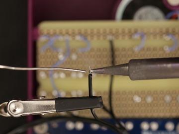
37 Powerboost 1000C Prep PowerBoost 1000C Next up we need to wire up the slide switch to the powerboost 1000c breakout. Secure the PCB to the helping third hands. We need to tin three pins so we can insert the wires from the slide switch. Heat up a pin with the tip of the soldering iron and apply solder. Tin pins 5V, G, GND, EN (we also did VBat but it isnt required). The pins should look like they have little soldered beads. Adafruit Industries Page 37 of 105


38 Wire Powerboost 1000C Secure the breakout to the third helping hands and position it close to enclosure. Heat up the pins on the breakout board with the soldering iron and insert the wire. You ll want to do this pretty quickly, about 5 seconds for each connection. Blue to GND and green to EN. You can skip the red wire, we don't need it. The photo shows red wire to BAT, but you don't need to connect this wire, the circuit will function without the red wire. Adafruit Industries Page 38 of 105


39 Thread Mounting Holes It's a good idea to thead the holes on the PCB to make it easier to mount to the enclosure. #4-40 3/8 flat phillips machine screws work best. Install PowerBoost 1000C With the wires on the powerboost soldered, you can release it from the third helping hands. It s a good idea to tuck the wires underneath the board before mounting it. Position the breakout over the bottom enclosure with the USB port facing the cut out. You ll want to tuck the three wires from the slide switch underneath the PowerBoost 1000c. The stand-offs should give you enough clearance. Adafruit Industries Page 39 of 105

40 Mount PowerBoost 1000C You ll need #4-40 ⅜ Phillips flat machine screws to mount the board to the enclosure. Hold the breakout board in place while you insert and fasten two #4-40 machine screws into the enclosure. Test PowerBoost 100C Plug in the JST cable from the rechargeable battery into the JST port. Flip the slide switch on to test if the circuit is working. The blue LED should turn on, indicating the battery is charged and ready. If everything lights up, disconnect the battery from the breakout board. If not, double check your wiring. Adafruit Industries Page 40 of 105


41 PAM8302 Prep PAM8302 Get the amp breakout secured to the panavise jr. Heat up the pins and apply some solder to all but the SD pin on the breakout. Adafruit Industries Page 41 of 105


42 PAM8302 Wires Measure and cut two 30AWG wires to about the length of the PCB. Strip the ends off each wire and tin the tips. Adafruit Industries Page 42 of 105

43 Thread PAM8302 Just like the powerboost PCB, it's a good idea to thread the mounting hole with a machine screw. We only need one hole threaded since we're using a single screw to secure the PCB to the enclosure. Solder Wires to PAM8302 Secure the PCB and solder the red wire to Vin pin and the blue wire to GND. Adafruit Industries Page 43 of 105


44 Mount PAM to enclosure Fit the breakout over the spot near the powerboost 1000c and line up the holes. Hold the PCB in place while you fasten a single #4-40 3/8 flat phillips machine screw. Adafruit Industries Page 44 of 105

45 Solder power to PAM8302 Solder up the red wire from Vin to 5V on the powerboost 1000c. Then connect the blue wire from Gnd to G on the powerboost 1000c. Adafruit Industries Page 45 of 105


46 Pi Audio Cut Pi Audio wires Measure and cut up two wires for connecting to the audio jack on the Pi, to the audio input on the PAM8302. Strip and Tin Wires Strip off the ends of each wire and tin the tips. Quick tip, you can secure both wires to a helping third hand so you can solder them all at once. Adafruit Industries Page 46 of 105

 can be indicated by seeing there's no traces connected to it. The positive (red wire) connection has visible traces.")
47 Tin Audio pins on Pi Next up we need to prep the solder points on the Pi to make it easier to solder our audio wires. Start by securing the Pi to the panavise jr downside up. Locate the audio jack and find the two solder spots for the positive and ground. Add a small amount of solder to these points. Solder Audio Wires to Pi Hit those points with the iron and solder the wires to positive and ground. The ground (white wire) can be indicated by seeing there's no traces connected to it. The positive (red wire) connection has visible traces. Adafruit Industries Page 47 of 105
 to A+ pin and the ground (white wire) to the A- pin on the PAM8302 Adafruit Industries https://learn.")
48 Solder Audio wires to PAM8302 Place the Pi into the base with the audio jack facing amp. Wire the positive (red wire) to A+ pin and the ground (white wire) to the A- pin on the PAM8302 Adafruit Industries Page 48 of 105


49 Mount Pi Hold the Pi in place while you insert and fasten four #4-40 3/8 flat phillips machine screws into the mounting holes. Adafruit Industries Page 49 of 105

50 Mounted Pi The screws should be fastened all the way so they're flush with the surface of the case. Adafruit Industries Page 50 of 105

51 Speaker Prep Metal Speaker Secure the speaker on the helping third hands (it has a magnet so just let it stick to one of the grabbers). Hit the solder joints and remove the wires. Be careful not to touch the magnet with the soldering iron tip! Adafruit Industries Page 51 of 105


52 Prep New Wires for Speaker Sit the two case parts close to each other to guage wire length and cut two pieces. Strip the tips of each wire and add solder to tin the tips. Adafruit Industries Page 52 of 105
 Adafruit Industries https://learn.adafruit.")
53 Solder Wires to Speaker Heat up the solder points on the speaker and connect the wires. The positive and negative symbols are indicated on the speaker. If it's not, follow the photo to reference the polarity (left is negative, right is positive.) Adafruit Industries Page 53 of 105


54 Install Speaker Position the speaker into the bottom corner of the enclosure. There's a circular indent with slits near the rounded corner of the case. That's where the speaker needs to go. The tolerance should be sized to fit the speaker tightly. Adafruit Industries Page 54 of 105

55 Connect Speaker wires to PAM8302 Solder the wires from the speaker to the audio out pins on the PAM8302. Adafruit Industries Page 55 of 105


56 2.4 PiTFT Install Header Insert the header that came with the PiTFT into the PCB. Use a piece of fun tac to hold the header in place while you solder. Adafruit Industries Page 56 of 105


57 Secure Header Solder the pins on the GPIO to seure the header to the PCB. The solder joints should look like little herseys kisses. Adafruit Industries Page 57 of 105


58 Remove Tac Remove the tac from the GPIO header. Ball it up and save it for the next project, it's served it's purpose! Add Buttons Insert five tactile switch buttons into the designated spots on the PiTFT PCB. They snap fit and will hold in place. Secure the PCB to a panavise jr and solder the buttons to secure them. Adafruit Industries Page 58 of 105


59 Trim buttons Snip the excess leads from the buttons the PiTFT PCB. These bits are sharp and could scratch the components. Adafruit Industries Page 59 of 105


60 Disable GPIO 18 Lite By default, the 2.4' PiTFT uses GPIO 18 to turn on/off the backlight on the display. In this build we're using GPIO 18 as a input button, so we need to cut the trace located on the back of the PCB, labled #18 Lite. Use a hobby knife to cut the trace. Prep Display PCB With the GPIO header and buttons soldered, go ahead and flip over the display so the two parts are side by side. Adafruit Industries Page 60 of 105


61 Peel Use your nail or hobby knife to peel the orange colored sticker backing. Remove and peel both pieces. Adafruit Industries Page 61 of 105
62 Stick Display Flip over the display and line it up with the screen outline on the PCB. Press down on the screen to make the adhesive stick to the PCB. You might also want to use some double-sided tape if the side tape pieces are not strong enough Adafruit Industries Page 62 of 105


63 Pi Cable Connect Pi Cable Line up the white wire on the ribbon cable with the white arrow on the PiTFT PCB. Press firmly on the connector to plug it into the pins. Adafruit Industries Page 63 of 105


64 Remove Pi Cable Connector Grab your set of flush cutters and snip off the connector the other end. Adafruit Industries Page 64 of 105


65 Peel Cable Peel apart each strand of wire from the cable like you would with stringy cheese. Peel it just enough so they're still some ribbon near the fold. Adafruit Industries Page 65 of 105


66 Mount Display Install display buttons Now is a good time to insert that strip of buttons printed in Ninjaflex. The buttons should fit into the cuts on the enclosure. Adafruit Industries Page 66 of 105


67 Install PiTFT Fit the PiTFT into the enclosure and line up the buttons and mounting holes. Grab four #4-40 3/8 flat phillips machine screws. Adafruit Industries Page 67 of 105


68 Mount PiTFT Hold the PiTFT in place while you insert and secure four machine screws into the PCB. These should fasten all the way through the PCB and the standoffs. Adafruit Industries Page 68 of 105
69 Perma-Proto Using Half-size Perma-Proto The perma-proto PCB is a lot like a breadboard. The rows are all linked together, while the columns are not. There's two power rails on the top and very bottom that include ground and voltage (indicated by blue and red lines). The columns are indicated by numbers (1-30) while the rows are indicated by letters (A-J). The half-size PCB has two separated centers in the center (A-E and F-J). Getting familiar with these labels will help you install the buttons and manage soldering wires. Adafruit Industries Page 69 of 105
 Mark the first column across (including rail) Mark row 26 down (including rail) Cut Perma-Proto I used a Dremel with a thin cut attachment to saw")

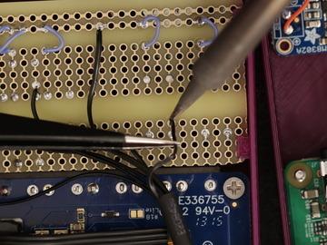
70 Mark Perma-Proto We need cut the PCB down so it can fit inside the enclosure. Before we do that, let's mark up on the PCB and draw guidelines. Mark the first row down (including rail) Mark the first column across (including rail) Mark row 26 down (including rail) Cut Perma-Proto I used a Dremel with a thin cut attachment to saw the excess pieces off the PCB. I recommend taking safety precausions when doing this. Do it in a well ventilated area (outside). Use safety glasses and a breathing mask. Secure the PCB to panavise jr. Always cut away from you. Clean dust from work area. If you're not satisfied with the sharp edge, use can use a grinding bit to round off the corners. Adafruit Industries Page 70 of 105


71 Install buttons (Two Action Buttons) Insert the four 6mm tactile buttons into the perma-proto and form the D-pad. Two 12mm square will be the "A" and "B" buttons. Adafruit Industries Page 71 of 105

72 Install buttons (Four action buttons) If you're making the four-button layout, insert eight 6mm tactile buttons to the perma-proto PCB. Reference the photo above to get the correct spots for each button. Solder buttons to PCB The buttons should hold in place once inserted into the PCB (if they don't, you can bend the legs to hold them in place). Flip it over so the bottom is face up and secure the PCB to the Panavise jr. Adafruit Industries Page 72 of 105


73 Prep Ground Wires We need to create short wires to connect the buttons to the ground rail. These wires should be pretty short about 10mm in length. You'll need to create 5 of them. Strip the tips off each wire and tin them. Adafruit Industries Page 73 of 105

.")

74 Solder Ground Wires For each button you'll need to tin the closest pin to the power rail and the ground pin. Since the rows are all linked together, we can just solder the pins that are closed to each other. The only button that doesn't is that up button (which we'll make a longer wire). Up Button Ground Wire The up button for the d-pad is the only button that doesn't use a short wire because its on the top section. We'll need to create a longer wire to connect it to the ground rail. Adafruit Industries Page 74 of 105

75 Trim legs Let's go ahead and snip the points legs from the PCB. This will ensure our perma-proto doesn't puncher or scratch any of the other components. 2-Button Layout OK now we have the perma-proto trimmed, the buttons solder in place and ground wires, we're ready to wire up the PiCable to the perma-proto PCB. Adafruit Industries Page 75 of 105

76 This is a good place to take a break. The next section contains lots more stripping, tinning and soldering! 4-Button Layout If you're doing the 4-button version, here's a photo to reference the wired connections. Each button has a wire connected to the ground rail. Note, the PiCable is already wired to the buttons. Adafruit Industries Page 76 of 105


77 Buttons Connect Pi Cable to Powerboost Grab the wires from the pi cable and locate wire #2 and #6. Wire #1 is the white colored one. Isolate these two wires and strip the tips off. Secure them to one of the grabbers on the third helping hand Apply some solder to tin them. Solder wire #2 to the positive pin on the Powerboost. Solder wire #6 to the negative pin on the Powerboost. Adafruit Industries Page 77 of 105


78 Soldered Power Now we should have power wired up from the Pi Cable to the powerboost 1000c. Wire #2 is actually pin 5V on the Pi, wire and #6 is ground. Adafruit Industries Page 78 of 105


79 Cut extra wires short Let's go ahead and cut the wires we won't be using short. Be sure to reference the circuit diagram and double, triple check each wires. Trimming these short will helps keep everything tidy and orangized. If your making the four button version, DO NOT cut wire #3 and #5!! Adafruit Industries Page 79 of 105
. Adafruit Industries https://learn.adafruit.")
80 Heat Shrink Pi Cable Speaking of being organized and tidy, adding a piece of heat shrinking tubing to the pi cable wires keeps them together. I didn't actually heat it though (depending on the sizing you may want to apply heat to well, shrink it). Adafruit Industries Page 80 of 105


81 Install Ninjaflex Buttons Insert the ninjaflex d-pad into the enclosure with the cut out. No special orientation here, its symmetrical so it should just fit. Place the A and B ninjaflex button set over the two 12mm tactile buttons on the perma-proto. These should have a tight fit. Adafruit Industries Page 81 of 105


82 Install Perma-Proto OK, grab the PCB and position it over the enclosure. Notice those clips on the inner walls of the enclosure? Those are going to hold the PCB in place. So position and orient the PCB with the appropriate buttons going into the right spots. The PCB needs to be inserted at an angle so that it can fit into place. Insert the PCB with the A and B button side going in first - the PCB should go underneath the clip. Ensure the d-pad is still in place while inserting the perma-proto PCB. Carefully angle it into place. You need to fit the ninjaflex AB buttons into the cutouts, then press down the PCB to fit into place. This takes a little force and finesse. The clips are fairly strong, so you don t need to be super gentle. Adafruit Industries Page 82 of 105


83 Wire Ground Let s connect the Pi Cable to the ground on the Perma- Proto. We can use a single ground wire from the Pi Cable and solder it to the ground rail on the Perma- Proto PCB. You can count and pull on the wires to determine which one to use. Wire #9 on the Pi Cable is associated with a ground connection. Adafruit Industries Page 83 of 105


84 Wire Left Button Find an available pin on the perma-proto that is linked to the left button. This should be on the opposite pin of the button where we wired ground. Locate wire #7 on the pi cable and position near it the left button. Measure how long it needs to be and cut short - leave a bit of slack so it s easier to solder. Strip and tin the wire. Then solder the wire to the perma-proto PCB. Adafruit Industries Page 84 of 105


85 Adafruit Industries Page 85 of 105


86 Wire Right Button Now that you did the first button, you ll be able to do the song and dance easier. Let s locate wire #11 on the pi cable - this is going to the right button. Just like we did on the left button, measure how long it needs to be, then cut, strip and tin. Solder this one to the one of the available pins in the same row of the right button. Wire Up Button Up next, it s the up button! Locate wire #12 and do the song and dance of measuring, cutting, stripping, tipping and soldering. Adafruit Industries Page 86 of 105


87 Adafruit Industries Page 87 of 105


88 Wire Down Button Locate wire #13 and solder this one to the down button. You know the drill! Adafruit Industries Page 88 of 105


89 Wire A Button Get wire #15 and connect this one to the A button. Double check to see you re selecting the correct button - orientation might mess with you a little after soldering all those wires. Adafruit Industries Page 89 of 105


90 Wire B button Adafruit Industries Page 90 of 105


91 OK now we should be left with just one wire - Safe to assume its wire #16 which will connect to the B button Adafruit Industries Page 91 of 105

.")
92 Wired Perma-Proto to Pi Cable It s starting to look finished after soldering all those wires. It s a good idea to double check all the buttons, pins and wires to ensure everything is correct. If you got any of them mixed, it is possible to remap them in software. But make sure ground is ground and nothing is intersecting (ie, two inputs wired to a single button). Adafruit Industries Page 92 of 105
 to the button you'd like to be \"Y\". That s all the soldering for this project. Congratulations, you are now a master solderer!")
93 Perma-Proto (Four button layout) If your making the four button version, you'll need to connect Wire #3 (GPIO 2) to the button you want to be "X". Connect wire #5 (GPIO 3) to the button you'd like to be "Y". That s all the soldering for this project. Congratulations, you are now a master solderer! Next up, we need to add the battery and close the enclosure. Almost done! Adafruit Industries Page 93 of 105


94 Assembly Final Wire Check It s a good idea to check all the wiring before closing it up. It is relatively easy to open and adjust but you should consider reviewing all the connections. If you think you have too much excess wire, now would be a good time to can trim them down. Plug Battery Adafruit Industries Page 94 of 105


95 Get the 2000mAh battery and insert the cable to the JST port on the powerboost 1000c. You might want to bend it at a right-angle so you can fit it in the case. Tack Battery I added a small piece of fun-tak to the back of the battery so it stick the back of the Perma-Proto PCB. This fun-tak stuff from loctite works really well cause it hold it in place, but easy to remove and doesn t leave behind any sticky gunk. Stick Battery Adafruit Industries Page 95 of 105


96 Go ahead and stick the battery onto the Perma-Proto PCB. Installed Battery Seems to be the best place for the battery. I would recommend wrapping this up in gaffers tape but when I did that it no longer fit, so at least you know now. We snipped off all the pointy stuff anyway, so it should be safe. Also note there s actually not too much force or pressuring being applied to the battery when it s enclosed. Close GPIO headers Adafruit Industries Page 96 of 105


97 With two hands, you want to pick up both parts of the enclosure and start closing it together. The first thing you wanna do is line up the header pins from the Pi to the socket on the PiTFT. Once their lined up, squeeze the two parts together to connect it. Wire Kink Check The top section should be closed now, leaving the bottom and sides a bit open. This is where you need to make sure none of the wires are outside the enclosure - it s easy to close it up and kink a wire when doing this. You ll most likely get the two magnets to snap together here since they re pretty strong. Adafruit Industries Page 97 of 105


98 Fasten Last Screw OK we re totally almost finished. Grab a single #4-40 ⅜ flat phillips machine screw and insert it into the bottom corner on the back of the enclosure. Hold the two parts together while you fasten the screw all the way through the enclosure. The whole screw will go inside the enclosure and fasten two standoffs together. This single screw keeps the two halves together. The magnet keeps the other corner closed while the top is closed with the aid of the GPIO header. And thats about it! Adafruit Industries Page 98 of 105
99 Final Build This build was a lot easier to wire and assemble than the previous PiGRRL projects. Using the perma-proto and tactile buttons in my opinion are more hassle free and ultimately feel better, too. There s a bit of extra room in the enclosure for other components and buttons, so feel encouraged to customize. The audio out of the Pi A+ isn't the best quality so there may be some hissing. You can minimize this by increasing the volume on the Pi as much as possible using alsamixer and/or the emulator's sound controls and adjusting the audio amp volume down to a comfy level I Made One, YES! If you made one, we want to see it!! We ask that you please share it with us. Send us a photo on twitter, better yet posit it on Thingiverse - Take photos of your build and post a make on the thingiverse page ( We'll feature your build on our 3D Hangouts show! You can even share it with us on Adafruit Show & Tell show! Post it on any social channel - use hastags #PiGRRL #Adafruit so we can find it easily. Adafruit Industries Page 99 of 105

100 RetroPie: Improving Emulator Performance On single-core Raspberry Pi boards like the Model A+ and Pi Zero, emulation speed is sometimes less than stellar the screen may update like molasses, or sound may be choppy. Let s look at some ideas to fight back All of these methods require a USB keyboard attached. The directions shown here are for RetroPie 4.1, but the same general ideas apply to other versions and possibly even other emulation packages, the steps will just be different. Overclocking Most Raspberry Pi boards can handle some overclocking running the processor slightly faster than its official speed. Too fast though, and the system can become unstable and crash. Due to manufacturing variances, every single board is slightly different in this regard you ll need to do some experimentation to find the fastest reliable setting for your specific board. Restart after making any changes and try running some games for several minutes to really put the system through its paces. You can access the raspi-config utility from the RetroPie configuration screen, or press F4 to exit to a command line and run sudo raspi-config manually. raspi-config is keyboard-based, mostly using the arrows and enter keys; arcade controls, if connected, probably won t have the intended effect. Different Pi models offer different overlock settings. On the Model B+ being tested here, the Medium setting seems quite reliable. Other board types may overclock automatically and there s nothing to adjust here. Adafruit Industries Page 100 of 105

. This brings up a menu similar to raspi-config, it operates with the keyboard, not arcade buttons.")
101 If you re using a PiTFT display, the core frequency setting should not exceed 300 MHz; the display will glitch and may not work at all. So avoid the higher overclock settings if using one of these screens, or manually edit the file /boot/config.txt to fine-tune various system frequencies individually. Choosing an Alternate Emulator When launching a game, there s a brief moment when it s possible to access some launch options When you see this launching screen, press the space bar (or any other key that generates an actual keycode not a meta key like shift or control). This brings up a menu similar to raspi-config, it operates with the keyboard, not arcade buttons. The first option lets you select an alternate emulator program (if available). For example, RetroPie 4.1 includes two different NES emulators: lr-fceumm (the default) and lr-nestopia. Different emulators make tradeoffs with regard to performance and accuracy of the emulation. Adafruit Industries Page 101 of 105


102 Try an alternative and see how it performs (use the Launch option). The selection you make will stick it is not necessary to use this menu every time, unless you want to switch back to the original emulator choice. There s also an option to use an alternate emulator only for specific ROMs, if you have different needs for different games. The above steps are fairly quick and easy. If they meet your needs, consider the job done! If it s still not quite the performance you need, the situation gets more involved These next steps require a network connection. On a Model A+ or Pi Zero, that usually requires a USB hub and an Ethernet or WiFi adapter, along with some configuration (the RetroPie 4.1 configuration menu includes WiFi setup). Alternately, if you have a spare Model B+ around, that s easy to get on an Ethernet network move the SD card over Adafruit Industries Page 102 of 105
103 there for setup, then move it back to the target system when done. Installing Additional Emulators Some bleeding edge emulators might offer better performance than the stock options provided by RetroPie. As with the Alternate Emulators above, it sometimes comes with a tradeoff in accuracy (hence their non-inclusion), so you ll need to experiment and decide if it s worth it. From the RetroPie configuration screen, select RetroPie Setup, which switches to another of these keyboardbased menus. Select Manage packages, then either Manage optional packages or Manage experimental packages. You ll get a list of various emulators and/or games that aren t normally installed by default. lrquicknes was an optional package for NES emulation it s faster than the others too fast, in fact, so I ended up not using it but that s all part of the experimentation process. Choose the Install from binary option to install the selected package. Don t bother with the source option it s very time consuming and usually provides no benefit. Adafruit Industries Page 103 of 105

104 Updating Emulators to Latest Versions Sometimes you just need the newest-and-shiniest version of an installed emulator to provide the best available performance Adafruit Industries Page 104 of 105
7 Portable Multitouch Raspberry Pi Tablet
 7 Portable Multitouch Raspberry Pi Tablet Created by Ruiz Brothers Last updated on 2017-02-27 04:13:53 PM UTC Guide Contents Guide Contents Overview Portable Raspberry Pi Tablet 7" Multitouch Display Parts
Portable Apple Watch Charger
 Portable Apple Watch Charger Created by Ruiz Brothers Last updated on 2017-10-22 09:58:04 PM UTC Guide Contents Guide Contents Overview Smart Charging Prerequisite Guides Parts, Tool & Supplies Circuit
PiGRRL 2. Created by Ruiz Brothers. Last updated on :41:35 AM UTC
 PiGRRL 2 Created by Ruiz Brothers Last updated on 2018-05-24 08:41:35 AM UTC Guide Contents Guide Contents Overview Raspberry Pi Retro Game Console Easier to build! Project Expectations Adafruit Parts
Mini Mac Pi. Created by Ruiz Brothers. Last updated on :43:27 PM UTC
 Mini Mac Pi Created by Ruiz Brothers Last updated on 2018-08-22 03:43:27 PM UTC Guide Contents Guide Contents Overview Build Your Own Mac Pi How it Works Project Advisory Challenges and Expectations Prerequisite
7" Portable HDMI Monitor
 7" Portable HDMI Monitor Created by Ruiz Brothers Last updated on 2017-05-29 05:47:14 PM UTC Guide Contents Guide Contents Overview DIY Monitor Connect to a Raspberry pi Use as a second monitor Camera
Feather Weather Lamp. Created by Ruiz Brothers. Last updated on :54:26 PM UTC
 Feather Weather Lamp Created by Ruiz Brothers Last updated on 2018-08-22 03:54:26 PM UTC Guide Contents Guide Contents Overview Weather Reactive Pixels Prerequisite Guides Parts Tools & Supplies Circuit
FPV Mini Display. Created by Ruiz Brothers. Last updated on :00:18 PM UTC
 FPV Mini Display Created by Ruiz Brothers Last updated on 2017-07-19 01:00:18 PM UTC Guide Contents Guide Contents Overview Mini FPV monitor Adafruit Parts Tools and Supplies Circuit Diagram Electronics
DIY Bluetooth Gamepad
 DIY Bluetooth Gamepad Created by Ruiz Brothers Last updated on 2016-09-03 02:23:21 AM UTC Guide Contents Guide Contents Overview Prerequisite Guides Expectations Parts Tools & Supplies Circuit Diagram
3D Printed Case for Adafruit Feather
 3D Printed Case for Adafruit Feather Created by Ruiz Brothers Last updated on 2018-08-22 03:59:38 PM UTC Guide Contents Guide Contents Overview Adafruit Feather Box New Update! Check out the TFT Feather
LED Eyes. Created by Ruiz Brothers. Last updated on :50:55 AM UTC
 LED Eyes Created by Ruiz Brothers Last updated on 2018-01-13 05:50:55 AM UTC Guide Contents Guide Contents Overview Parts, Tools and Supplies Enameled Copper Magnet Wire 11 meters / 0.1mm diameter Adafruit
3D Printed 20w Amplifier Box
 3D Printed 20w Amplifier Box Created by Ruiz Brothers Last updated on 2018-02-26 06:48:02 PM UTC Guide Contents Guide Contents Overview Prerequisite Guide Tools & Supplies Parts 3D Printing Print in your
Solar Boost Bag. Created by Becky Stern. Last updated on :44:55 PM UTC
 Solar Boost Bag Created by Becky Stern Last updated on 2018-08-22 03:44:55 PM UTC Guide Contents Guide Contents Overview 3D Design Files Customize Design Assemble Circuit Prepare Solar Panel Enclosure
Trinket NeoPixel LED Longboard
 Trinket NeoPixel LED Longboard Created by Ruiz Brothers Last updated on 2017-10-02 06:00:32 PM UTC Guide Contents Guide Contents Overview Parts Tools & Supplies Prerequisite Guides 3D Printing PLA Material
3D Printed 20w Amplifier Box
 3D Printed 20w Amplifier Box Created by Noe & Pedro Ruiz Last updated on 2014-04-22 03:01:38 PM EDT Guide Contents Guide Contents Overview Prerequisite Guide Tools & Supplies Parts 3D Printing Print in
Raspberry Pi Pipboy 3000
 Raspberry Pi Pipboy 3000 Created by Ruiz Brothers Last updated on 2017-08-09 01:44:21 AM UTC Guide Contents Guide Contents Overview Functional Cosplay Props Electronic Parts & Components Tools & Supplies
Trellis 3D Printed Enclosure
 Trellis 3D Printed Enclosure Created by Ruiz Brothers Last updated on 2018-08-22 03:39:07 PM UTC Guide Contents Guide Contents Overview Parts Tools & Supplies Modeling 123D Design Customize Measuring Parts
3D Printed Google AIY Voice Kit
 3D Printed Google AIY Voice Kit Created by Ruiz Brothers Last updated on 2018-01-09 12:47:26 AM UTC Guide Contents Guide Contents Overview 3D Print a DIY AI enclosure for the Raspberry PI! Parts, Tools
3D Printed Camera LED Ring
 3D Printed Camera LED Ring Created by Ruiz Brothers Last updated on 2018-08-22 03:39:34 PM UTC Guide Contents Guide Contents Overview DIY LED Ring Light Prerequisite Guide: Parts List: Tools & Supplies
Boomy The Boombox. Created by Ruiz Brothers. Last updated on :52:13 PM UTC
 Boomy The Boombox Created by Ruiz Brothers Last updated on 2017-09-05 08:52:13 PM UTC Guide Contents Guide Contents Overview Boomy The Boombox AdaBox 004 Parts 3D Printing 3D Printed Parts Enclosure Design
Circuit Playground Combadge
 Circuit Playground Combadge Created by Ruiz Brothers Last updated on 2017-10-22 10:42:02 PM UTC Guide Contents Guide Contents Overview What's a Combadge? DIY Combadge How Does It Work? Make It How You
Simple LED Unicorn Horn
 Simple LED Unicorn Horn Created by Ruiz Brothers Last updated on 2018-08-22 03:56:14 PM UTC Guide Contents Guide Contents Overview 3D Printed Unicorn Horn Want More Magic/Colors? Great For Beginners Parts
This isn t a complete guide, but it should show you enough to figure out how I did this and that.
 I wanted to fit a Raspberry Pi running Retropie into a Gameboy Advance SP case. I didn t want to cut any new holes and it had to close up completely; no wires sticking out, no extra buttons in places they
3D Printed Bone Conduction Transducer Box
 3D Printed Bone Conduction Transducer Box Created by Ruiz Brothers Last updated on 2018-08-22 03:40:25 PM UTC Guide Contents Guide Contents Overview Tools & Supplies Parts 3D Printing Circuit Diagram Stereo
Bluetooth Controlled NeoPixel Headphones
 Bluetooth Controlled NeoPixel Headphones Created by Ruiz Brothers Last updated on 2017-03-09 07:38:05 PM UTC Guide Contents Guide Contents Overview Smart LED HeadPhones Prerequisite Guides Parts Tools
NeoPixel Bike Light. Created by Ruiz Brothers. Last updated on :43:46 PM UTC
 NeoPixel Bike Light Created by Ruiz Brothers Last updated on 2018-11-15 07:43:46 PM UTC Guide Contents Guide Contents Overview 3D Printed Headlight Adafruit's Feather Platform Circuit Python Powered Parts
Adafruit Prototyping Pi Plate. Created by Ladyada
 Adafruit Prototyping Pi Plate Created by Ladyada Guide Contents Guide Contents Overview Solder it! User Manual Buy Adafruit Prototyping Pi Plate 2 3 4 14 17 Adafruit Industries http://learn.adafruit.com/adafruit-prototyping-pi-plate
Neon LED Signs. Created by John Park. Last updated on :11:09 PM UTC
 Neon LED Signs Created by John Park Last updated on 2018-08-22 04:11:09 PM UTC Guide Contents Guide Contents Overview Parts Materials Tools Build the Sign Driver Preparation Solder the Circuit Solder the
Guardian Shield+ Zelda Breath of the Wild
 Guardian Shield+ Zelda Breath of the Wild Created by Ruiz Brothers Last updated on 2018-08-22 04:01:50 PM UTC Guide Contents Guide Contents Overview Articulating Handle Rechargeable Prerequisite Guides
3D Printed LED Knuckle Jewelry
 3D Printed LED Knuckle Jewelry Created by Ruiz Brothers Last updated on 2015-02-20 09:31:06 AM EST Guide Contents Guide Contents Overview Prerequisite Guides Parts Tools & Supplies 3D Printing Filament
Cup o' Sound. Created by Becky Stern. Last updated on :30:06 PM EST
 Cup o' Sound Created by Becky Stern Last updated on 2015-02-18 01:30:06 PM EST Guide Contents Guide Contents Overview Circuit Diagram Load Sound and Prepare Components Solder Circuit and Assemble Use it!
PyPortal View Master Created by Ruiz Brothers. Last updated on :51:28 AM UTC
 PyPortal View Master Created by Ruiz Brothers Last updated on 2019-03-13 11:51:28 AM UTC Overview In this project we re building a view master inspired device using Adafruit s PyPortal. The eyepiece makes
Adafruit PowerBoost 500 Shield
 Adafruit PowerBoost 500 Shield Created by lady ada Last updated on 2018-08-22 03:43:27 PM UTC Guide Contents Guide Contents Overview Pinouts DC/DC Boost section Indicator LEDs Charging section Power Switch
Circuit Playground Yoyo
 Circuit Playground Yoyo Created by Ruiz Brothers Last updated on 2018-01-13 05:56:02 AM UTC Guide Contents Guide Contents Overview 3D Printed NeoPixel Yoyo History of the Yo-Yo Expectations Parts Tools
No-Sew LED Wristband. Created by Kathy Ceceri. Last updated on :23:40 PM UTC
 No-Sew LED Wristband Created by Kathy Ceceri Last updated on 2018-11-13 09:23:40 PM UTC Guide Contents Guide Contents Overview Playing with LED Options Suggested Parts List -- Electronics Suggested Materials
FLORA TV-B-Gone. Created by Becky Stern. Last updated on :32:57 PM UTC
 FLORA TV-B-Gone Created by Becky Stern Last updated on 2018-08-22 03:32:57 PM UTC Guide Contents Guide Contents Overview Parts Tutorials Transistors Resistors LEDs Pushbutton Program it Power Fabric pinwheel
Bunny Ears with MakeCode
 Bunny Ears with MakeCode Created by Erin St Blaine Last updated on 2018-08-22 04:05:47 PM UTC Guide Contents Guide Contents Introduction Tools & Other Materials Programming with MakeCode Set Up the Light
Audio Prank Gift Box. Created by Becky Stern. Last updated on :46:15 PM UTC
 Audio Prank Gift Box Created by Becky Stern Last updated on 2018-08-22 03:46:15 PM UTC Guide Contents Guide Contents Overview Circuit Diagram Prepare Components Build Circuit Wrap and Give 2 3 5 6 12 14
3D Printed LED Buckle
 3D Printed LED Buckle Created by Ruiz Brothers Last updated on 2018-08-22 03:38:02 PM UTC Guide Contents Guide Contents Overview Customize the Buckle Artwork, Design and Text Scale, Adjust and Combine
Zelda Thunder Helm. Created by Ruiz Brothers. Last updated on :46:52 PM UTC
 Zelda Thunder Helm Created by Ruiz Brothers Last updated on 2017-08-23 02:46:52 PM UTC Guide Contents Guide Contents Overview Zelda: Breath Of The Wild Parts, Tools and Supplies Proto-Pasta - Aromatic
Raspberry Pi Selfie Bot
 Raspberry Pi Selfie Bot Created by Sophy Wong Last updated on 2018-08-22 04:03:16 PM UTC Guide Contents Guide Contents Overview Parts & Supplies The Circuit Power Circuit Other Connections Laser Cutting
Adafruit Capacitive Touch Sensor Breakouts
 Adafruit Capacitive Touch Sensor Breakouts Created by Bill Earl Last updated on 2018-08-22 03:36:13 PM UTC Guide Contents Guide Contents Overview Momentary Toggle 5-Pad Momentary Assembly and Wiring Installing
i2c/spi LCD Backpack Created by lady ada Last updated on :11:04 PM UTC
 i2c/spi LCD Backpack Created by lady ada Last updated on 2017-08-16 05:11:04 PM UTC Guide Contents Guide Contents Overview Which LCD to Use? Wait - the backpack has 16 holes, but my LCD only has 14 pins!
3D Printing Guide: MakerBot Replicator 2X
 SOUTHERN POLYTECHNIC STATE UNIVERSITY 3D Printing Guide: MakerBot Replicator 2X Operating and Troubleshooting Guide Architecture Department 8/13/2014 Revision Table Version Dated Description By 1.00 06/25/2014
Crawling Animatronic Hand
 Crawling Animatronic Hand Created by Dano Wall Last updated on 2018-12-03 06:39:35 PM UTC Guide Contents Guide Contents Overview Parts Used Tools & Materials Prepare the Hand Your hand is now ready to
Ping Pong Ball Launcher
 Ping Pong Ball Launcher Created by Dano Wall Last updated on 2019-01-25 03:19:13 AM UTC Guide Contents Guide Contents Overview Electronic Parts Circuit Playground Express USB cable - USB A to Micro-B Alkaline
NeoPixel Manicure. Created by Sophy Wong. Last updated on :50:38 PM UTC
 NeoPixel Manicure Created by Sophy Wong Last updated on 2018-04-11 05:50:38 PM UTC Guide Contents Guide Contents Overview Parts & Supplies Tools Circuit Diagram Build the Circuit Measure Your Circuit Prepare
Infinity Mirror Valentine's Candy Box
 Infinity Mirror Valentine's Candy Box Created by Kathy Ceceri Last updated on 2019-02-07 09:44:54 PM UTC Guide Contents Guide Contents Overview Parts List -- Mini Box Version Chibitronics Color LEDs Add-On
'Sup Brows. Created by Kate Hartman. Last updated on :52:04 PM UTC
 'Sup Brows Created by Kate Hartman Last updated on 2018-08-22 03:52:04 PM UTC Guide Contents Guide Contents Overview Circuit Bluetooth Test Upload the Code Place the Sensor View Sensor Values Via Bluetooth
DIY Circuit Playground Shields
 DIY Circuit Playground Shields Created by Dave Astels Last updated on 2018-08-22 04:05:06 PM UTC Guide Contents Guide Contents Overview Small Alligator Clip Test Lead (set of 12) Small Alligator Clip to
Tent Lantern. Created by Timothy Reese. Last updated on :17:25 AM UTC
 Tent Lantern Created by Timothy Reese Last updated on 2017-07-14 05:17:25 AM UTC Guide Contents Guide Contents Overview Things you'll need: What You'll Learn: 3D Printing Code Assembly Wiring Diagram Soldering
Glowing Smokey Skull. Created by Ruiz Brothers. Last updated on :03:40 PM UTC
 Glowing Smokey Skull Created by Ruiz Brothers Last updated on 2018-08-22 04:03:40 PM UTC Guide Contents Guide Contents Overview Easy DIY Halloween Props Electronic Halloween! Circuit Playground NeoPixels
Bluetooth LE MIDI Controller
 Bluetooth LE MIDI Controller Created by Ruiz Brothers Last updated on 2017-03-01 08:40:08 PM UTC Guide Contents Guide Contents Overview A Different Looking MIDI Controller BLE MIDI Drum Machine How Does
Crickit Carnival Bumper Bot
 Crickit Carnival Bumper Bot Created by John Park Last updated on 2018-08-22 04:08:52 PM UTC Guide Contents Guide Contents Overview Parts Materials and Tools Build the Bumper Bot Cut the Cardboard Chassis
Stumble-Bot. Created by Dano Wall. Last updated on :04:06 AM UTC
 Stumble-Bot Created by Dano Wall Last updated on 2018-09-06 05:04:06 AM UTC Guide Contents Guide Contents Overview Simply Stumbling We Have the Technology Other Supplies Leg Assembly Front Legs Back Legs
Phone-Activated Talking Dog Collar
 Phone-Activated Talking Dog Collar Created by Phillip Burgess Last updated on 2017-01-24 08:28:00 PM UTC Guide Contents Guide Contents Overview Circuit Diagram & Code Leather Collar & Greebles Assemble
Crickit Powered Holiday Diorama
 Crickit Powered Holiday Diorama Created by Isaac Wellish Last updated on 2018-12-04 12:49:07 AM UTC Guide Contents Guide Contents Overview Prerequisite Guides Adafruit Parts Tools and Materials Wiring
Hammer Time Mini Golf Hazard with Crickit
 Hammer Time Mini Golf Hazard with Crickit Created by John Park Last updated on 2018-07-09 06:47:53 AM UTC Guide Contents Guide Contents Overview Please Hammer, Don't Hurt Em Parts Materials & Tools Program
Circuit Playground Express Head-Tilt Ears
 Circuit Playground Express Head-Tilt Ears Created by Dave Astels Last updated on 2018-10-09 04:07:03 PM UTC Guide Contents Guide Contents Overview Parts Circuit Playground Express Micro servo Lithium Ion
Adafruit AMG8833 8x8 Thermal Camera Sensor
 Adafruit AMG8833 8x8 Thermal Camera Sensor Created by Justin Cooper Last updated on 2017-11-27 10:00:27 PM UTC Guide Contents Guide Contents Overview Pinouts Power Pins: Logic pins: Assembly Prepare the
Webcam Cover-Up Lego brick with Adabot Mini Fig
 Webcam Cover-Up Lego brick with Adabot Mini Fig Created by Ruiz Brothers Last updated on 2018-08-22 04:06:44 PM UTC Guide Contents Guide Contents Overview 3D Printing What If I Don't Have A 3D Printer?
3DPrinted Custom Keycaps
 3DPrinted Custom Keycaps Created by Ruiz Brothers Last updated on 2016-09-05 07:20:30 PM UTC Guide Contents Guide Contents Overview Custom Keycaps Easy to install Accessibility Project Expectations Parts
Magical Mistletoe. Created by Leslie Birch. Last updated on :45:29 PM UTC
 Magical Mistletoe Created by Leslie Birch Last updated on 2018-08-22 03:45:29 PM UTC Guide Contents Guide Contents Overview Tools & Supplies Circuit Diagram Test the Sensor Prepare Parts Attach LED Sequins
Mystical LED Halloween Hood
 Mystical LED Halloween Hood Created by Becky Stern Last updated on 2017-09-28 11:13:20 PM UTC Guide Contents Guide Contents Overview NeoPixel GEMMA circuit Arduino Code NeoPixel Überguide: Arduino Library
AdaBox 005. Created by Tyler Cooper. Last updated on :08:13 PM UTC
 AdaBox 005 Created by Tyler Cooper Last updated on 2017-09-27 08:08:13 PM UTC Guide Contents Guide Contents Introduction Hi there! Who is this for? Who isn't this for? Who are you? Unboxing AdaBox 005
Android GBoard Morse Code Control with Circuit Playground Express
 Android GBoard Morse Code Control with Circuit Playground Express Created by Dave Astels Last updated on 2018-08-22 04:10:30 PM UTC Guide Contents Guide Contents Overview Parts Materials for the box Installing
BLE Light Switch with Feather nrf52840 and Crickit
 BLE Light Switch with Feather nrf52840 and Crickit Created by John Park Last updated on 2019-02-15 07:06:19 PM UTC Guide Contents Guide Contents Overview Parts Adafruit Feather nrf52840 Express Adafruit
Adabot Operation Game
 Adabot Operation Game Created by John Park Last updated on 2018-08-22 04:11:17 PM UTC Guide Contents Guide Contents Overview Parts Materials & Tools Build the Operating Table Print the Board and Pieces
Paper Airplane Launcher
 Paper Airplane Launcher Created by Dano Wall Last updated on 2018-08-27 08:36:14 PM UTC Guide Contents Guide Contents Overview A Launching Platform The Electronics Materials Build the Launcher Attach Motors
Crickit Dancing Marionette Kit Created by Dano Wall. Last updated on :03:11 PM UTC
 Crickit Dancing Marionette Kit Created by Dano Wall Last updated on 2019-04-04 07:03:11 PM UTC Overview This project demonstrates how to build a robotic marionette that is controlled with four arcade-style
Adafruit Pi Cobbler Kit
 Adafruit Pi Cobbler Kit Created by lady ada Last updated on 2018-08-22 03:30:27 PM UTC Guide Contents Guide Contents Overview Solder it! Buy a Pi Cobbler Kit! Downloads 2 3 5 15 16 Adafruit Industries
Reindeer Mask with Animated Eyes
 Reindeer Mask with Animated Eyes Created by Dano Wall Last updated on 2018-12-05 10:50:10 PM UTC Guide Contents Guide Contents Overview Parts Adafruit HalloWing M0 Express Convex Plastic Lens with Edge
CircuitPython Media Dial
 CircuitPython Media Dial Created by Ruiz Brothers Last updated on 2018-02-07 05:00:25 AM UTC Guide Contents Guide Contents Overview Prerequisite Guides Adafruit Trinket M0 - for use with CircuitPython
Wind Blowing Emoji Prop
 Wind Blowing Emoji Prop Created by John Park Last updated on 2018-08-22 04:05:17 PM UTC Guide Contents Guide Contents Overview Code it with MakeCode Start Up Variables On Loud Sound If - Else Iterate Debounce
FLORA Pixel Brooch. Created by Becky Stern. Last updated on :19:07 PM EST
 FLORA Pixel Brooch Created by Becky Stern Last updated on 2015-02-20 01:19:07 PM EST Guide Contents Guide Contents Overview Connect first signal wire Connect power and ground wires Add more pixels Program
Prophet 600 GliGli mod
 Prophet 600 GliGli mod Created by Collin Cunningham Last updated on 2018-08-22 04:04:56 PM UTC Guide Contents Guide Contents Overview What you'll need Program the Teensy++ Modify the Teensy++ Prep header
Qi Wireless Recharging Battery Case
 Qi Wireless Recharging Battery Case Created by Rick Winscot Last updated on 2015-11-04 12:50:13 PM EST Guide Contents Guide Contents Introduction Disassembly Guts! Testing 2 3 5 10 16 Adafruit Industries
Fiddy - the FTDI Clip
 Fiddy - the FTDI Clip Created by Timothy Reese Last updated on 2018-08-22 03:57:42 PM UTC Guide Contents Guide Contents Overview FTDI is Great! Things you'll need: What You'll Learn: 3D Printing Assembly
Fiddy - the FTDI Clip
 Fiddy - the FTDI Clip Created by Timothy Reese Last updated on 2016-11-22 09:18:04 PM UTC Guide Contents Guide Contents Overview FTDI is Great! Things you'll need: What You'll Learn: 3D Printing Assembly
Naughty or Nice Machine
 Naughty or Nice Machine Created by Brian Corteil Last updated on 2018-08-22 03:45:31 PM UTC Guide Contents Guide Contents Overview It knows if you have been Naughty or Nice! Make It! Parts The Case The
NeoPixel LED Cortana Costume
 NeoPixel LED Cortana Costume Created by Ruiz Brothers Last updated on 2018-08-22 03:43:43 PM UTC Guide Contents Guide Contents Overview How it Works Project Advisory Prerequisite Guides Parts & Components
Magnetic shoelaces. Created by Ruiz Brothers. Last updated on :31:02 PM UTC
 Magnetic shoelaces Created by Ruiz Brothers Last updated on 2016-12-29 04:31:02 PM UTC Guide Contents Guide Contents Overview Parts, Tools and Supplies 3D Printing Download and 3D Print Slice Settings
Slider Crank Mechanism -- from Cardboard and Craft Sticks
 Slider Crank Mechanism -- from Cardboard and Craft Sticks Created by John Park Last updated on 2018-08-22 04:07:21 PM UTC Guide Contents Guide Contents Overview Materials Tools Build the Slider Crank Build
Solder Dispenser Adabot Head
 Solder Dispenser Adabot Head Created by Ruiz Brothers Last updated on 2017-01-04 02:15:15 PM UTC Guide Contents Guide Contents Overview Solder Dispenser Parts Solder Spool - 1/4 lb SAC305 RoHS lead-free
Bike Wheel POV Display
 Bike Wheel POV Display Created by Becky Stern Last updated on 2017-09-12 03:10:38 PM UTC Guide Contents Guide Contents Overview Parts and Tools Circuit Diagram Prep LEDs & Breadboard Code Solder Circuit
TRON Bag. Created by Becky Stern
 TRON Bag Created by Becky Stern Last updated on 2018-08-22 03:30:39 PM UTC Guide Contents Guide Contents Overview Tools Design Soldering Sewing Detailing Splitting Finishing Buy EL! Forums 2 3 5 7 12 15
LED Lightbox. Created by Sam Clippinger. Last updated on :50:00 AM UTC
 LED Lightbox Created by Sam Clippinger Last updated on 2016-09-03 01:50:00 AM UTC Guide Contents Guide Contents Overview TL;DR Skill Level Parts List Yellow sticker reads: "Bad planning on your part does
Adafruit TPL5110 Power Timer Breakout
 Adafruit TPL5110 Power Timer Breakout Created by lady ada Last updated on 2017-12-11 06:28:19 AM UTC Guide Contents Guide Contents Overview Pinouts Power Pins Control Pins Assembly Prepare the header strip:
Lie Ren's Stormflower Gun Blade
 Lie Ren's Stormflower Gun Blade Created by Ruiz Brothers Last updated on 2017-04-02 05:39:24 PM UTC Guide Contents Guide Contents Overview Cosplay Props with NeoPixels Triggered Lighting Effects DIY Electronics
FeatherWing Proto, Doubler and Tripler
 FeatherWing Proto, Doubler and Tripler Created by lady ada Last updated on 2018-11-15 10:39:12 PM UTC Guide Contents Guide Contents Overview FeatherWing Proto FeatherWing Doubler FeatherWing Tripler Proto
DIY Wireless DDR Dance Pad with Bluefruit EZ-Key
 DIY Wireless DDR Dance Pad with Bluefruit EZ-Key Created by Paul Beaudet Last updated on 2018-08-22 03:40:07 PM UTC Guide Contents Guide Contents Overview What's DDR? Materials Cheapo method - As Shown
Pushrod Garage. Created by John Park. Last updated on :07:30 PM UTC
 Pushrod Garage Created by John Park Last updated on 2018-08-22 04:07:30 PM UTC Guide Contents Guide Contents Overview Parts & Materials Tools Pushrod Mechanism Code it with MakeCode Functions On Start
Adafruit DRV2605 Haptic Controller Breakout
 Adafruit DRV2605 Haptic Controller Breakout Created by lady ada Last updated on 2018-08-20 03:28:51 PM UTC Guide Contents Guide Contents Overview Pinouts Power Pins I2C Pins Other! Assembly Prepare the
Camera LED Ring Light
 Camera LED Ring Light Created by Ruiz Brothers Last updated on 2017-05-09 06:07:12 PM UTC Guide Contents Guide Contents Overview NeoPixel Ring Light Dedicated white LED Prerequisite Guides Parts Tools
Clockwork Goggles. Created by John Park. Last updated on :03:10 PM UTC
 Clockwork Goggles Created by John Park Last updated on 2018-08-22 04:03:10 PM UTC Guide Contents Guide Contents Overview Assemble Circuit and Goggles CircuitPython Setup and Code Rock the Goggles 2 3 6
DIY Custom American Girl Doll Prosthetics
 DIY Custom American Girl Doll Prosthetics Created by Ruiz Brothers Last updated on 2017-11-15 08:53:16 PM UTC Guide Contents Guide Contents Overview Parts Tools and Supplies 3D Printing 3D Printed Parts
Celebration Spectacles
 Celebration Spectacles Created by Becky Stern Last updated on 2018-08-22 03:45:59 PM UTC Guide Contents Guide Contents Overview Circuit Diagram Assemble Circuit Test and Glue Wear 'em! 2 3 6 7 10 14 Adafruit
Bandolier of Light. Created by Becky Stern. Last updated on :16:17 PM EST
 Bandolier of Light Created by Becky Stern Last updated on 2015-02-19 02:16:17 PM EST Guide Contents Guide Contents Overview 3D Design File Ninjaflex STLs Slicer Settings Clean Up Modify Design Solder Circuit
Adafruit Mini TFT " 160x80
 Adafruit Mini TFT - 0.96" 160x80 Created by lady ada Last updated on 2017-11-17 05:56:10 PM UTC Guide Contents Guide Contents Overview Pinouts Assembly Prepare the header strip: Add the breakout board:
CPX Mystery Dreidel. Created by Kathy Ceceri. Last updated on :51:40 PM UTC
 CPX Mystery Dreidel Created by Kathy Ceceri Last updated on 2018-12-04 02:51:40 PM UTC Guide Contents Guide Contents Overview Parts List -- Electronics Circuit Playground Express USB cable - USB A to Micro-B
FeatherWing Proto and Doubler
 FeatherWing Proto and Doubler Created by lady ada Last updated on 2016-09-19 05:11:36 PM UTC Guide Contents Guide Contents Overview FeatherWing Proto FeatherWing Doubler Proto Pinout Proto Pinout Duplicated