MiniPOV4 - DIY Full-Color Persistence of Vision & Light-Painting Kit
|
|
|
- Hilary Doyle
- 5 years ago
- Views:
Transcription

1 MiniPOV4 - DIY Full-Color Persistence of Vision & Light-Painting Kit Created by lady ada Last updated on :41:06 PM UTC
2 Guide Contents Guide Contents Overview Make it! Testing Upload Images Install Windows Drivers Download Software If there's a problem Make your own images! More Usage Tips Adjusting the POV speed Re-programming the chip (advanced) More Pins! Downloads Software Firmware, PCB files Parts List Preparations ( Solder up Solder It! Adafruit Industries Page 2 of 66
3 Overview Angel demos the MiniPOV4! The latest and greatest MiniPOV kit to hit the streets - MiniPOV4! We have added full color RGB LEDs to the kit as well USB programmability to make this the easiest, most fun Persistence-of-Vision & Light Painting kit ever. Adafruit Industries Page 3 of 66

4 Learn to solder by building this easy kit. About 20 components are soldered onto the custom PCB using a soldering iron, solder and some basic hand tools. Learn as you go, starting with the easier parts and working your way up to the more challenging ones. Takes about an hour or two to complete following our detailed tutorial Once finished, you'll have a little battery-powered light painting kit! Insert three AAA batteries (not included, pick some up here or use any you have lying around the house) and wave around to create light trails. The way our eyes work, as the LEDs move we see the image as if it were floating in the air. You can also use a camera with a medium-long exposure to create a light painting as shown above. Design your own 8-pixel tall images in any drawing program and import them into our software to upload your own custom designs. Simply plug into your computer's USB port and run our Processing sketch - it works on any Mac or Windows computer! (Linux support still being tested) Adafruit Industries Page 4 of 66

5 Each order comes as a kit of parts. Some soldering and tools are required to put together but its a nice learning kit and with patience and a couple of hours can be assembled by any beginner. Adafruit Industries Page 5 of 66

6 Make it! Building this kit is a great way to learn soldering and electronics assembly. Its best to build this kit when you have a few hours to devote to the kit, so that you aren't rushed. Making a mistake in soldering can take a bit of time to fix so by following each step fully you will have a great experience without frustration! Adafruit Industries Page 6 of 66

7 Testing Before you go further, make sure you have three AAA batteries, they'll need to be good batteries but can be alkaline or rechargables. Insert the batteries into the battery holder Adafruit Industries Page 7 of 66

8 And flip the ON/OFF switch to ON Wait three seconds for the MiniPOV to 'boot' and you'll see the red, green and blue LEDs light up in order Adafruit Industries Page 8 of 66
9 Then the LEDs will flicker white. This is how it looks when not moving. Turn off the lights and wave the MiniPOV around to see the light display! Angel demos the MiniPOV4! OK next up we'll check to make sure we can connect to it on the computer before finishing up. Adafruit Industries Page 9 of 66

10 Upload Images Install Windows Drivers If you are using Windows, you'll need to install the USB driver for the MiniPOV4. Drivers are only required for Windows, if you are using a Mac or Linux, drivers are not required! For details on installing the drivers for Windows XP, 7, 8 etc... please read this page! ( Turn off the MiniPOV4 and plug in the USB port to a USB cable and your computer. Now turn on the MiniPOV4. You should get this popup (or similar) Once recognized, windows will ask you for a driver location. Point it at the uncompressed zip file. When done, you will be able to see the USBtiny device in the Device manager (you can get to the device manager from the Control Panel) Mac users do not need any driver installation! Download Software Once you know the MiniPOV is blinking right, we can upload brand new images! Start by downloading the MiniPOV4 Adafruit Industries Page 10 of 66

11 programming software. Uncompress the zip file and save it to your desktop! You'll also need a copy of Processing - a graphics framework we'll be using to do all the image conversion. You can grab Processing for free here - please download version ( In addition, please download the controlp5 library for processing ( you can download it directly by clicking below Run Processing once and then quit. This will create the processing sketchbook folder. Now you will have to install the ControlP5 library. Start by unzipping/uncompressing the ControlP5.zip folder you downloaded. Inside will be two folders, one called controlp5 and one file with install instructions. Follow the install instructions, for windows & mac users, go to your Documents Folder and find the new Processing subfolder in there Adafruit Industries Page 11 of 66

 Adafruit Industries https://learn.adafruit.")
12 Create a new folder in there called libraries Inside that folder, place the ControlP5 folder So filewise, you will have My Documents/Processing/libraries/ConrolP5/library.properties (and the other library files!) Adafruit Industries Page 12 of 66


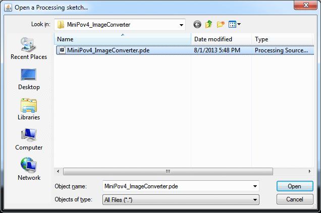
13 Whew. Now make sure you quit any copies of Processing and start it up again from scratch. Open up the uncompressed MiniPOV4 Image Converter pde file Adafruit Industries Page 13 of 66


14 Select the Sketch->Run menu item to start it up! Click Open Image File to load a new 8-pixel tall PNG file - lets use the minipov4test.png Click Download To Minipov4 to send the image over. You will see the LEDs light up red/green/blues as the download completes Adafruit Industries Page 14 of 66


15 If there's a problem If you get an error message, check: is the MiniPOV kit turned on and plugged into USB? remember you need to turn it on with batteries in when its plugged into USB! Make your own images! Use your favorite image software to create your own images. For best results, make sure its 8-pixels tall, and 8-bit color. Save as a PNG file if possible. Remember that black pixels are "LEDs off" and white pixels are "LEDs on" Adafruit Industries Page 15 of 66
16 More Usage Tips Adjusting the POV speed Remember soldering in that blue potentiometer? You can twist that to adjust the 'speed' of the POV effect. Depending on how you are doing your light painting you can adjust it up and down. Re-programming the chip (advanced) The chip in the MiniPOV4 is programmed with a USB bootloader that looks like a USBtinyISP. That means: if you are an advanced user you can use the bootloader with avrdude or Arduino IDE and selecting USBtiny as the upload protocol! The EEPROM section of the chip is what holds the 'image', the firmware is in "Arduino-ese" and can be adjusted and reprogrammed by selecting USBtinyISP as the programmer and holding down shift when clicking upload More Pins! There are a few unused pins, we broke them out on the edge of the PCB in case you want to connect sensors, switches or other devices. The unused pins are the serial UART rx/tx pins and the i2c/analog pins A4 and A5 (in arduino-pin notation) Adafruit Industries Page 16 of 66
17 Downloads Software Download the image converter/uploader tool (requires Processing 2.0+) ( Download Processing here ( Windows driver (signed drivers, works with Windows 8) ( Firmware, PCB files Check out the GitHub repository for more advanced source files including PCB files, bootloader code, etc. ( Adafruit Industries Page 17 of 66

18 Parts List 1 x Programmed 8-bit Microcontroller - Atmega328P-PU 4x 2.2K 5% 1/4W Resistor 1x 0.1uF Ceramic Capacitor Adafruit Industries Page 18 of 66

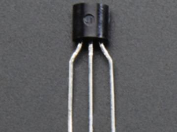
19 2x 100uF/6V Capacitor 1x 2x3 Male Header - 0.1" 3x PN General Purpose Transistor Adafruit Industries Page 19 of 66


20 1x 28-pin socket 10x 47ohm 5% 1/4W Resistor 1x Foam Tape - Rectangle Adafruit Industries Page 20 of 66

21 1x 12MHz Ceramic Oscillator 2x 3.6v Zener Diode Adafruit Industries Page 21 of 66


22 1x USB B-type Jack 8x Diffused 'Piranha' RGB LEDs 1x MiniPOV 4 PCB Adafruit Industries Page 22 of 66
 Adafruit Industries https://learn.adafruit.")
23 1x 10k Breadboard Trim Potentiometer ( 1x 3xAAA Battery Holder with On/Off Switch and 2-pin JST ( Adafruit Industries Page 23 of 66
tools There are a few tools that are required for assembly. None of these tools are included. If you don't have them, now would be a good time to borrow or purchase them.")
24 Preparations Learn how to solder with tons of tutorials! ( Don't forget to learn how to use your multimeter too! ( ( There are a few tools that are required for assembly. None of these tools are included. If you don't have them, now would be a good time to borrow or purchase them. They are very very handy whenever assembling/fixing/modifying electronic devices! I provide links to buy them, but of course, you should get them whereever is most convenient/inexpensive. Many of these parts are available in a place like Radio Shack or other (higher quality) DIY electronics stores. Soldering iron Any entry level 'all-in-one' soldering iron that you might find at your local hardware store should work. As with most things in life, you get what you pay for. Upgrading to a higher end soldering iron setup, like the Hakko FX-888 that we stock in our store ( will make soldering fun and easy. Do not use a "ColdHeat" soldering iron! They are not suitable for delicate electronics work and can damage the kit (see here ( Click here to buy our entry level adjustable 30W 110V soldering iron ( Click here to upgrade to a Genuine Hakko FX-888 adjustable temperature soldering iron. ( Adafruit Industries Page 24 of 66
 (http://adafru.it/145). Click here to buy a spool of lead-free solder (http://adafru.it/734). Adafruit Industries https://learn.")
25 Solder You will want rosin core, 60/40 solder. Good solder is a good thing. Bad solder leads to bridging and cold solder joints which can be tough to find. Click here to buy a spool of leaded solder (recommended for beginners) ( Click here to buy a spool of lead-free solder ( Adafruit Industries Page 25 of 66
 Click here to buy a top of the line multimeter. (http://adafru.it/308) Click here to buy a pocket multimeter. (http://adafru.it/850) it/71) Click here to buy a top of the line multimeter.")

26 Multimeter You will need a good quality basic multimeter that can measure voltage and continuity. Click here to buy a basic multimeter. ( Click here to buy a top of the line multimeter. ( Click here to buy a pocket multimeter. ( Multimeter You will need a good quality basic multimeter that can measure voltage and continuity. Click here to buy a basic multimeter. ( Click here to buy a top of the line multimeter. ( Click here to buy a pocket multimeter. ( Multimeter You will need a good quality basic multimeter that can measure voltage and continuity. Click here to buy a basic multimeter. ( Click here to buy a top of the line multimeter. ( Click here to buy a pocket multimeter. ( Adafruit Industries Page 26 of 66
.")
.")
27 Flush Diagonal Cutters You will need flush diagonal cutters to trim the wires and leads off of components once you have soldered them in place. Click here to buy our favorite cutters ( Solder Sucker Strangely enough, that's the technical term for this desoldering vacuum tool. Useful in cleaning up mistakes, every electrical engineer has one of these on their desk. Click here to buy a one ( Adafruit Industries Page 27 of 66
. Adafruit Industries https://learn.adafruit.")
28 Helping Third Hand With Magnifier Not absolutely necessary but will make things go much much faster, and it will make soldering much easier. Pick one up here ( Adafruit Industries Page 28 of 66
.")
 and color stripes.")
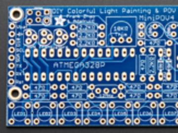
29 Solder up Solder It! The first step is to solder the kit together. If you've never soldered before, check the Preparation page for tutorials and more. Place the PCB in a vise, and turn on the soldering iron. Make sure you have all the tools you'll need to assemble the kit ( If you don't know how to solder, we suggest checking out the videos in the link above. They're quite good! Keep them in a window so you can watch and review as you work through the kit The first part we will place is a resistor - this is a small oval tan thing with two wires (leads) and color stripes. The stripes are red red red which indicates a 2.2K resistor. This particular resistor is used in the MiniPOV4 kit to let the computer know we've plugged in the USB port when it comes time to upload a new image. The resistor goes right in the middle, over the silkscreen text that says 2.2K. Resistors are non-polar which means they don't have a direction: you don't have to worry about putting it in 'backwards' because they work the same either way Adafruit Industries Page 29 of 66

 and one of the wires of the resistor (lead)")

30 Bend the resistor into a staple and slip it onto the top of the Printed Circuit Board. Bend the little leads out so that you can flip over the PCB and the resistor will stay in place. The resistor sits flat right up against the PCB and the leads hold it in place when bent Now you'll solder! Place the flat of the soldering iron tip against the silver ring (pad) and one of the wires of the resistor (lead) at the same time for 2 seconds. This will heat them both up to degrees. Then poke the end of the solder so that it flows into the hole and forms a solder joint. Adafruit Industries Page 30 of 66

31 Solder joints should be smooth and shiny and fill the entire pad, wicking up to the lead. You shouldn't be able to wiggle the wire and have it move in the hole. Adafruit Industries Page 31 of 66


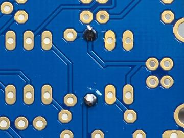
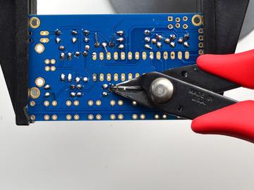
32 Now we will get rid of all that excess wire. Use your diagonal nippers to clip the wire just above the end of the solder joint. There should be almost no 'wire' sticking out. Adafruit Industries Page 32 of 66


33 Next up we'll do the other three 2.2K resistors. These three resistors are the base current resistors for the transistors. They are used to balance out the amount of current going into the transistors so that they are not overloaded by the microcontroller. They go three in a row all next to each other. Again, the colors are red red red and they are non-polar so they can go in 'either way' Adafruit Industries Page 33 of 66


34 Flip over the kit and solder in these three resistors. You can do one at a time, or all three at once if you feel up to it! Adafruit Industries Page 34 of 66

35 Check your soldering after done to make sure each solder point is nice and neat and shiny! Adafruit Industries Page 35 of 66

36 Now you can clip the long legs, all six! Adafruit Industries Page 36 of 66


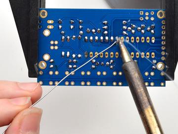
37 Now that we are done with the 2.2k resistors we'll move onto the 47 ohm resistors. These smaller resistors are used to set the brightness of the LEDs. LEDs need current-setting resistors so that they don't burn out from too much current! We also have two we use for the USB data connection, plus 8 for the 8 LEDs makes for 10 total. These resistors have the yellow violet black color stripes. There's quite a few so we're going to do half at a time. Start by placing these four. Solder up all 8 solder points. You can clip the leads as you go if they're in the way. Adafruit Industries Page 37 of 66


38 Check your work, then clip the leads off cleanly. Adafruit Industries Page 38 of 66


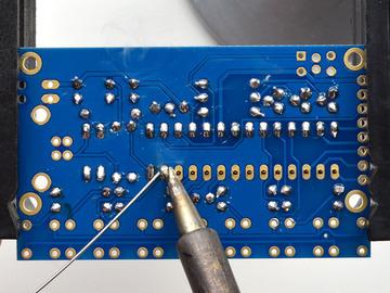
39 Place the remaining 47 ohm resistors over their silkscreens as shown. Solder the remaining resistors! Finally we have done all the resistor components Adafruit Industries Page 39 of 66

40 Adafruit Industries Page 40 of 66

41 Check your soldering work, and then clip the leads Adafruit Industries Page 41 of 66


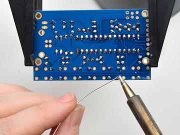
42 Next up we will do the Zener Diodes - these are semiconductor devices that only let current go one way. These particular ones are used for the USB interface to keep the voltages stable on the USB data lines. Zener Diodes are directional! So you should pay attention to make sure you place them correctly. The Diodes have a little black mark at one end. Place the dioes in the two spots next to the USB jack. You'll notice on the silkscreen for the diodes there's a white stripe mark. That white stripe matches the same end of the diode with the black stripe. Check the photos to make sure you have the two diodes in the right way! Flip the board over and solder in the two diodes. Adafruit Industries Page 42 of 66

43 Adafruit Industries Page 43 of 66


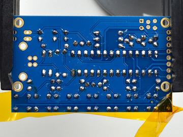
44 Check your work - then clip the leads. Next is the ceramic capacitor. Capacitors helps stabilize the output voltage, and filters out high frequency noise so that the battery voltage nice and smooth. Adafruit Industries Page 44 of 66

45 Place the capacitor so that the 2 legs (leads) slide thru the two metal holes in the PCB (pads). The capacitor will sit flat against the PCB. The capacitor goes right below the text on the top of the board, its the little yellow blobby thing. Next are the two electrolytic capacitors. These help smooth both the input and output voltages, to keep them stable during the up-conversion. They are used for low frequency noise, and are often paired with a ceramic capacitor. Adafruit Industries Page 45 of 66


46 Electrolytic capacitors are polarized and must be placed correctly or the circuit will not work. Each capacitor has a side with a stripe on it, here its a white stripe with a big - symbol on it. This is the negative (-) side. This goes in the hole that isn't marked with a + Adafruit Industries Page 46 of 66


47 Check the photos to make sure you have the side with the strip in the right way before continuing Now you can solder all three capacitors in at once! Clip the leads when done Adafruit Industries Page 47 of 66


48 Next up we'll move beyond capacitors and resistors and diodes with only two pins and move up to transistors! Transistors are like the power-tools of electronics, they are strong so you can use them to 'heavy lifting'. In this case we use three transistors to control the Red Green and Blue colors of the 8 LEDs all at once. Since they have to drive 8 LEDs at once, you can't do it from a plain microcontroller pin - they're weaklings. These transistors amplify the signal over 100x so they are plenty strong to handle 8 LEDs. Adafruit Industries Page 48 of 66


49 Transistors have a rounded side and a flat side. When placing these parts, make sure the rounded side of the transistor matches the rounded silkscreen image. You will have to bend the legs a bit to fit into the triangular shape so they dont sit nice and flat against the printed circuit board. Adafruit Industries Page 49 of 66


50 Solder all three legs of a transistor. I like to solder in one, then clip the leads before moving onto the next one, so the leads dont get in the way of my soldering. Keep soldering! Finish all three transistors by carefully checking your work before continuing. Adafruit Industries Page 50 of 66

51 Adafruit Industries Page 51 of 66


 or frequency range (a radio tuner!")
52 Now we're moving to the point where we can place two components at a time. We'll be placing the Potentiometer and the 12MHz Crystal The potentiometer is the blue thing that goes near the top middle of the PCB. It can only fit on one way to match the silkdscreen The crystal oscillator goes in between the sets of resistors near the bottom, its orange and has three legs. It is symmetric so you can put it in 'either way' The potentiometer is a blue three-pin knob. It translates rotation into resistance. We use this part in the kit to set the speed of the LED blinking. potentiometers are often used in electronics to set things like voltage range (a volume knob!) or frequency range (a radio tuner!) Adafruit Industries Page 52 of 66
 it will be able to flip through all the LEDs at a consistent")

53 The 12MHz crystal is a time-keeper component. It is used by the main 'brains' of the chip to keep track of time. By having a crystal (sort of like the quartz crystal in a clock or watch) it will be able to flip through all the LEDs at a consistent speed. Flip over the board and solder in both 3-pin components. The leads are shorter than other parts so far but you should still clip them so they don't touch other pads by accident. Adafruit Industries Page 53 of 66

54 Adafruit Industries Page 54 of 66


55 OK now we're onto the big part that goes in the middle. That's where the microcontroller goes. Since the microcontroller has 28 pins, its best to use a socket to keep it in place. Its safer since that way you can always remove the microcontroller later. Also, although its best to put in the socket the right way, its not a big deal - you can always just make sure the chip goes in right! The silkscreen underneath the socket has a little notch in it. The socket also has a notch! so make sure that the notch in the socket lines up with the silkscreen. In the photo to the left, the notch is on the left side The leads are very short on a socket, if you have fingernails you can try bending over two corner legs to hold it in place. You can also use scotch tape from the top to hold it in place while you solder There's 28 pins to solder so go through them one by one, all must be soldered! Adafruit Industries Page 55 of 66

56 Adafruit Industries Page 56 of 66


57 There is no clipping to do when done Now we're onto the LEDs. The LEDs have four legs - one common lead and then one for the red, green and blue component LEDs. If you look at the LEDs you'll notice that one corner of each one has a flat notched corner. Make sure you check this for each LED! Adafruit Industries Page 57 of 66


58 When you place the LED into the PCB, maks sure the flat corner matches the silkscreen. In the photo to the left, the notch is in the north-west / top-left corner To make soldering easier, I suggest placing only four alternating LEDs to start. Adafruit Industries Page 58 of 66

59 The legs of the LEDs are very short, so you may want to tilt the board and tack-solder one pin of each LED with a little solder just to hold it in place. You can also use tape to hold it down! Adafruit Industries Page 59 of 66


60 Solder the four LEDs, making sure to do all four pins of each Adafruit Industries Page 60 of 66
61 Next up, do the other 4 LEDs - checking that each one has that flat corner in the right spot. I used tape on these four Adafruit Industries Page 61 of 66


62 Solder all of them, moving the tape out of the way as needed Adafruit Industries Page 62 of 66


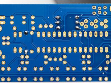
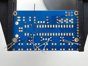
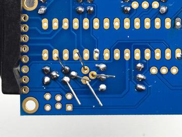
63 We're ready to move to the battery pack. The battery pack comes with a connector but we don't need it, so cut the two wires in half. You can discard the connector half. Make sure no batteries are in the holder! Use a pair of wire strippers to remove about 1/4" of wire insulation from the end of each wire. It's ok if its a little shorter or longer. Adafruit Industries Page 63 of 66


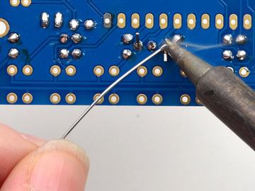
64 Use your soldering iron and a small amount of solder to tin the wire by melting a little solder into the bare wires. Tinning wires makes them much easier to solder later so make sure to do this step! The battery pack is now ready for attaching to the main circuit Adafruit Industries Page 64 of 66

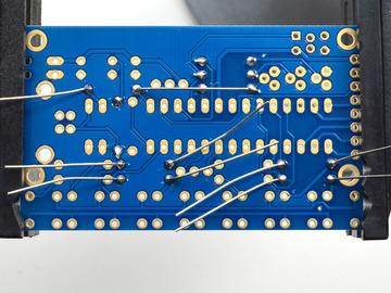
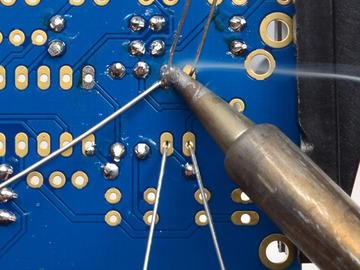
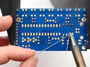
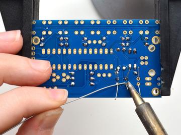
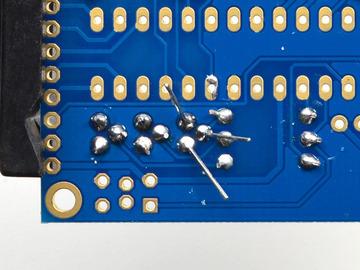
65 The battery pack has a red wire, thats the positive (+) pin - and a black wire, that's the negative (-) pin. Put the two wires into the large pads in the top right corner so that the red wire and black wire are in the right holes Adafruit Industries Page 65 of 66


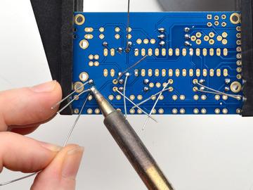
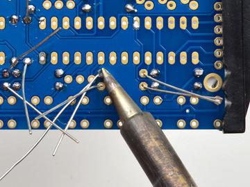
66 Solder both wires from the bottom. You can use tape to keep them in place if they move around too much. Adafruit Industries Last Updated: :41:01 PM UTC Page 66 of 66


67 To connect the MiniPOV4 to a computer, you'll need a USB connection. We'll now attach the USB connector, the big silver thing. When placing it, make sure that the 4 little legs don't get bent before going into the holes. They're thin so bend them back so that all four can be soldered. After making sure that all four little pins made it through, solder the two big "mechanical" pads - these are big holes that hold the connector in place. Use plenty of solder!

68 Then do the four little power and data connections. You do not need to clip the leads, they are quite short!


69 Finally we are going to insert the microcontroller chip. This is the 'brains' of the operation - it stores the image you want to display and times the flashing of the LEDs in the order you want. We're using an Atmel ATMega328 - commonly known as the chip that is the brains of the Arduino Uno board. Chips come from the factory with the legs in a bit of an A shape when we really need them to be more of an H shape - straight up and down. To make them fit in the socket, grip the chip from both ends and press the legs against a flat table to get rid of the angle. Do this for both sides, a little at a time, until you can see they are nice and parallel


70 You can now insert the chip. Make sure you insert the chip the right way! The chip has a small notch in one end, that notch needs to match the notch in the silkscreen. Hopefully if you soldered in the socket right, it will also match the notch in the silkscreen but either way, make sure the notch is on the left side when you hold it with the LEDs on the bottom as shown here Check your chip placement one last time before we continue onto testing! Note that you can read the text upright on the chip. OK now it's time to test!
DC & USB Boarduino Kits
 DC & USB Boarduino Kits Created by lady ada Last updated on 2018-08-22 03:34:24 PM UTC Guide Contents Guide Contents Overview Make It! Steps Preparation Prep (https://adafru.it/c06)tools DC Parts List
FLORA TV-B-Gone. Created by Becky Stern. Last updated on :32:57 PM UTC
 FLORA TV-B-Gone Created by Becky Stern Last updated on 2018-08-22 03:32:57 PM UTC Guide Contents Guide Contents Overview Parts Tutorials Transistors Resistors LEDs Pushbutton Program it Power Fabric pinwheel
i2c/spi LCD Backpack Created by lady ada Last updated on :11:04 PM UTC
 i2c/spi LCD Backpack Created by lady ada Last updated on 2017-08-16 05:11:04 PM UTC Guide Contents Guide Contents Overview Which LCD to Use? Wait - the backpack has 16 holes, but my LCD only has 14 pins!
Neon LED Signs. Created by John Park. Last updated on :11:09 PM UTC
 Neon LED Signs Created by John Park Last updated on 2018-08-22 04:11:09 PM UTC Guide Contents Guide Contents Overview Parts Materials Tools Build the Sign Driver Preparation Solder the Circuit Solder the
Adafruit 8x16 LED Matrix FeatherWing
 Adafruit 8x16 LED Matrix FeatherWing Created by lady ada Last updated on 2016-05-20 01:58:38 PM EDT Guide Contents Guide Contents Overview Pinouts Power Pins I2C pins Address Jumpers Changing Addresses
Adafruit MCP9808 Precision I2C Temperature Sensor Guide
 Adafruit MCP9808 Precision I2C Temperature Sensor Guide Created by lady ada Last updated on 2017-11-12 06:09:49 PM UTC Guide Contents Guide Contents Overview Pinouts Power Pins I2C Data Pins Optional Pins
FLORA and GEMMA ICSP. Created by Becky Stern. Last updated on :42:16 PM UTC
 FLORA and GEMMA ICSP Created by Becky Stern Last updated on 2018-08-22 03:42:16 PM UTC Guide Contents Guide Contents Overview Reprogram FLORA over ICSP Reprogram GEMMA over ICSP 2 3 4 9 Adafruit Industries
Adafruit Capacitive Touch Sensor Breakouts
 Adafruit Capacitive Touch Sensor Breakouts Created by Bill Earl Last updated on 2018-08-22 03:36:13 PM UTC Guide Contents Guide Contents Overview Momentary Toggle 5-Pad Momentary Assembly and Wiring Installing
Monochrome OLED Breakouts
 Monochrome OLED Breakouts Created by lady ada Last updated on 2018-01-02 08:35:47 PM UTC Guide Contents Guide Contents Overview Power Requirements OLED Power Requirements 5V- ready 128x64 and 128x32 OLEDs
Adafruit Mini TFT " 160x80
 Adafruit Mini TFT - 0.96" 160x80 Created by lady ada Last updated on 2017-11-17 05:56:10 PM UTC Guide Contents Guide Contents Overview Pinouts Assembly Prepare the header strip: Add the breakout board:
Adafruit Si7021 Temperature + Humidity Sensor
 Adafruit Si7021 Temperature + Humidity Sensor Created by lady ada Last updated on 2017-11-12 06:14:07 PM UTC Guide Contents Guide Contents Overview Pinouts Power Pins: I2C Logic pins: Assembly Prepare
Drawdio. Created by lady ada. Last updated on :42:04 AM UTC
 Drawdio Created by lady ada Last updated on 2017-07-14 05:42:04 AM UTC Guide Contents Guide Contents Overview Sketching with Hardware Drawdio: A pencil that lets you draw with music! Video! Credits Design
Adafruit Pi Cobbler Kit
 Adafruit Pi Cobbler Kit Created by lady ada Last updated on 2018-08-22 03:30:27 PM UTC Guide Contents Guide Contents Overview Solder it! Buy a Pi Cobbler Kit! Downloads 2 3 5 15 16 Adafruit Industries
Adafruit Si5351 Clock Generator Breakout
 Adafruit Si5351 Clock Generator Breakout Created by lady ada Last updated on 2017-06-02 07:54:50 PM UTC Guide Contents Guide Contents Overview Pinouts Power Pins I2C Pins Assembly Prepare the header strip:
Adafruit VL53L0X Time of Flight Micro-LIDAR Distance Sensor Breakout
 Adafruit VL53L0X Time of Flight Micro-LIDAR Distance Sensor Breakout Created by lady ada Last updated on 2017-12-28 11:56:14 PM UTC Guide Contents Guide Contents Overview Sensing Capablities Pinouts Power
Bike Wheel POV Display
 Bike Wheel POV Display Created by Becky Stern Last updated on 2017-09-12 03:10:38 PM UTC Guide Contents Guide Contents Overview Parts and Tools Circuit Diagram Prep LEDs & Breadboard Code Solder Circuit
FLORA and GEMMA ICSP. Created by Becky Stern. Last updated on :30:55 PM EST
 FLORA and GEMMA ICSP Created by Becky Stern Last updated on 2015-02-19 02:30:55 PM EST Guide Contents Guide Contents Overview Reprogram FLORA over ICSP Reprogram GEMMA over ICSP 2 3 5 10 Adafruit Industries
Adafruit APDS9960 breakout
 Adafruit APDS9960 breakout Created by Dean Miller Last updated on 2018-01-19 11:18:59 PM UTC Guide Contents Guide Contents Overview Pinouts Power Pins: Logic pins: Assembly Prepare the header strip: Add
Adafruit I2C FRAM Breakout
 Adafruit I2C FRAM Breakout Created by lady ada Last updated on 2017-07-14 05:38:45 AM UTC Guide Contents Guide Contents Overview Pinouts Power Pins: I2C Logic pins: Assembly Prepare the header strip: Add
1.8" TFT Display Breakout and Shield
 1.8" TFT Display Breakout and Shield Created by lady ada Last updated on 2017-11-17 05:51:22 PM UTC Guide Contents Guide Contents Overview Breakout Pinouts Breakout Assembly Prepare the header strip: Add
0.96" mini Color OLED
 0.96" mini Color OLED Created by lady ada Last updated on 2016-09-08 03:41:52 PM UTC Guide Contents Guide Contents Overview Power Wiring New Model Older Model Wiring the OLDER design (two rows of pins
MCP Bit DAC Tutorial
 MCP4725 12-Bit DAC Tutorial Created by lady ada Last updated on 2016-10-07 04:47:03 PM UTC Guide Contents Guide Contents Overview Wiring Using with Arduino Using the library Increasing the speed Download
MCP Bit DAC Tutorial
 MCP4725 12-Bit DAC Tutorial Created by lady ada Last updated on 2018-03-05 10:51:16 PM UTC Guide Contents Guide Contents Overview Wiring Arduino Code Using the library Increasing the speed CircuitPython
Introducing Adafruit Trellis
 Introducing Adafruit Trellis Created by lady ada Last updated on 2016-09-16 09:12:22 PM UTC Guide Contents Guide Contents Overview Adding LEDs Connecting Library reference Creating the objects Controlling
RGB LCD Shield. Created by lady ada. Last updated on :48:40 PM UTC
 RGB LCD Shield Created by lady ada Last updated on 2017-12-04 11:48:40 PM UTC Guide Contents Guide Contents Overview Parts List 1) Resistors 2) Potentiometer 3) Pushbuttons 4) i2c Port Expander Chip 5)
Adafruit Prototyping Pi Plate. Created by Ladyada
 Adafruit Prototyping Pi Plate Created by Ladyada Guide Contents Guide Contents Overview Solder it! User Manual Buy Adafruit Prototyping Pi Plate 2 3 4 14 17 Adafruit Industries http://learn.adafruit.com/adafruit-prototyping-pi-plate
Adafruit TPL5110 Power Timer Breakout
 Adafruit TPL5110 Power Timer Breakout Created by lady ada Last updated on 2017-12-11 06:28:19 AM UTC Guide Contents Guide Contents Overview Pinouts Power Pins Control Pins Assembly Prepare the header strip:
Adafruit MMA8451 Accelerometer Breakout
 Adafruit MMA8451 Accelerometer Breakout Created by lady ada Last updated on 2014-07-31 07:00:14 PM EDT Guide Contents Guide Contents Overview Pinouts (http://adafru.it/dln)power Pins I2C Pins INT and ADDR
NeoMatrix 8x8 Word Clock
 NeoMatrix 8x8 Word Clock Created by Andy Doro Last updated on 2017-10-10 04:10:51 AM UTC Guide Contents Guide Contents Overview Parts List Parts Tools Circuit Assembly Overview Uploading Code Understanding
Adafruit DRV2605 Haptic Controller Breakout
 Adafruit DRV2605 Haptic Controller Breakout Created by lady ada Last updated on 2018-08-20 03:28:51 PM UTC Guide Contents Guide Contents Overview Pinouts Power Pins I2C Pins Other! Assembly Prepare the
Adafruit PowerBoost 500 Shield
 Adafruit PowerBoost 500 Shield Created by lady ada Last updated on 2018-08-22 03:43:27 PM UTC Guide Contents Guide Contents Overview Pinouts DC/DC Boost section Indicator LEDs Charging section Power Switch
Adafruit DRV2605 Haptic Controller Breakout
 Adafruit DRV2605 Haptic Controller Breakout Created by lady ada Last updated on 2016-10-03 09:48:16 PM UTC Guide Contents Guide Contents Overview Pinouts Power Pins I2C Pins Other! Assembly Prepare the
NeoLoch. Inquisitor Core. Assembly Instructions (9/3/2015)
") NeoLoch Inquisitor Core Assembly Instructions (9/3/2015) Your kit should contain the following items. If you find a part missing, please contact NeoLoch for a replacement. Kit contents: 1 PCB 1 2.1mm DC
NeoLoch Inquisitor Core Assembly Instructions (9/3/2015) Your kit should contain the following items. If you find a part missing, please contact NeoLoch for a replacement. Kit contents: 1 PCB 1 2.1mm DC
Adafruit HUZZAH32 - ESP32 Feather
 Adafruit HUZZAH32 - ESP32 Feather Created by lady ada Last updated on 2017-07-14 02:14:00 AM UTC Guide Contents Guide Contents Overview Pinouts Power Pins Logic pins Serial pins I2C & SPI pins GPIO & Analog
Adafruit AMG8833 8x8 Thermal Camera Sensor
 Adafruit AMG8833 8x8 Thermal Camera Sensor Created by Justin Cooper Last updated on 2017-11-27 10:00:27 PM UTC Guide Contents Guide Contents Overview Pinouts Power Pins: Logic pins: Assembly Prepare the
Crickit Carnival Bumper Bot
 Crickit Carnival Bumper Bot Created by John Park Last updated on 2018-08-22 04:08:52 PM UTC Guide Contents Guide Contents Overview Parts Materials and Tools Build the Bumper Bot Cut the Cardboard Chassis
Infinity Mirror Valentine's Candy Box
 Infinity Mirror Valentine's Candy Box Created by Kathy Ceceri Last updated on 2019-02-07 09:44:54 PM UTC Guide Contents Guide Contents Overview Parts List -- Mini Box Version Chibitronics Color LEDs Add-On
Getting Started with FLORA
 Getting Started with FLORA Created by Becky Stern Last updated on 2018-01-03 04:31:24 AM UTC Guide Contents Guide Contents Overview Windows Driver Installation Manual Driver Installation Download software
Solar Boost Bag. Created by Becky Stern. Last updated on :44:55 PM UTC
 Solar Boost Bag Created by Becky Stern Last updated on 2018-08-22 03:44:55 PM UTC Guide Contents Guide Contents Overview 3D Design Files Customize Design Assemble Circuit Prepare Solar Panel Enclosure
Ping Pong Ball Launcher
 Ping Pong Ball Launcher Created by Dano Wall Last updated on 2019-01-25 03:19:13 AM UTC Guide Contents Guide Contents Overview Electronic Parts Circuit Playground Express USB cable - USB A to Micro-B Alkaline
Chirping Plush Owl Toy
 Chirping Plush Owl Toy Created by Becky Stern Last updated on 2018-11-21 08:56:55 PM UTC Guide Contents Guide Contents Overview Tools & Supplies Solder Circuit Arduino Code CircuitPython Code Assemble
FLORA Pixel Brooch. Created by Becky Stern. Last updated on :19:07 PM EST
 FLORA Pixel Brooch Created by Becky Stern Last updated on 2015-02-20 01:19:07 PM EST Guide Contents Guide Contents Overview Connect first signal wire Connect power and ground wires Add more pixels Program
Trellis 3D Printed Enclosure
 Trellis 3D Printed Enclosure Created by Ruiz Brothers Last updated on 2018-08-22 03:39:07 PM UTC Guide Contents Guide Contents Overview Parts Tools & Supplies Modeling 123D Design Customize Measuring Parts
Getting Started with FLORA
 Getting Started with FLORA Created by Becky Stern Last updated on 2014-12-12 02:30:15 PM EST Guide Contents Guide Contents Overview Download software Mac OSX Install Drivers! (Windows Only) Windows 8 Windows
Adafruit ATWINC1500 WiFi Breakout
 Adafruit ATWINC1500 WiFi Breakout Created by lady ada Last updated on 2018-01-29 08:25:04 PM UTC Guide Contents Guide Contents Overview Pinouts Power Pins SPI Pins Other SPI Interface Pins Assembly Prepare
Adafruit 1.27" and 1.5" Color OLED Breakout Board
 Adafruit 1.27" and 1.5" Color OLED Breakout Board Created by Bill Earl Last updated on 2017-11-17 05:54:22 PM UTC Guide Contents Guide Contents Overview Board Technical Details Assembly Prepare the header
Adafruit GPS Hat in Windows IoT Core
 Adafruit GPS Hat in Windows IoT Core Created by Rick Lesniak Last updated on 2017-01-01 08:17:19 PM UTC Guide Contents Guide Contents Overview Assembly GPSDemoApp Adafruit Class Library 2 3 4 6 13 Adafruit
IS31FL x9 Charlieplexed PWM LED Driver
 IS31FL3731 16x9 Charlieplexed PWM LED Driver Created by lady ada Last updated on 2018-01-10 06:31:05 PM UTC Guide Contents Guide Contents Overview Pinouts Power Pins I2C Data Pins Other Control Pins LED
Adafruit AM2320 Sensor
 Adafruit AM2320 Sensor Created by lady ada Last updated on 2018-03-07 09:49:28 PM UTC Guide Contents Guide Contents Overview Pinouts Arduino Usage Install Adafruit Sensor Download Adafruit_AM2320 Load
Prophet 600 GliGli mod
 Prophet 600 GliGli mod Created by Collin Cunningham Last updated on 2018-08-22 04:04:56 PM UTC Guide Contents Guide Contents Overview What you'll need Program the Teensy++ Modify the Teensy++ Prep header
Bunny Ears with MakeCode
 Bunny Ears with MakeCode Created by Erin St Blaine Last updated on 2018-08-22 04:05:47 PM UTC Guide Contents Guide Contents Introduction Tools & Other Materials Programming with MakeCode Set Up the Light
No-Sew LED Wristband. Created by Kathy Ceceri. Last updated on :23:40 PM UTC
 No-Sew LED Wristband Created by Kathy Ceceri Last updated on 2018-11-13 09:23:40 PM UTC Guide Contents Guide Contents Overview Playing with LED Options Suggested Parts List -- Electronics Suggested Materials
Adafruit 8x16 LED Matrix FeatherWing
 Adafruit 8x16 LED Matrix FeatherWing Created by lady ada Last updated on 2019-01-28 05:47:44 PM UTC Guide Contents Guide Contents Overview Pinouts Power Pins I2C pins Address Jumpers Changing Addresses
Getting Started with FLORA
 Getting Started with FLORA Created by Becky Stern Last updated on 2015-05-13 01:00:11 PM EDT Guide Contents Guide Contents Overview Download software Blink onboard LED Blink onboard NeoPixel Install the
NeoPixel Ring Bangle Bracelet
 NeoPixel Ring Bangle Bracelet Created by Becky Stern Last updated on 2017-09-28 11:14:48 PM UTC Guide Contents Guide Contents Overview Circuit Diagram Build it! Arduino Code CircuitPython Code Planning
Adafruit WINC1500 WiFi Shield for Arduino
 Adafruit WINC1500 WiFi Shield for Arduino Created by lady ada Last updated on 2017-11-27 07:04:37 PM UTC Guide Contents Guide Contents Overview Pinouts SPI Interface Pins WiFi Control Pins SD Card Interface
Mystical LED Halloween Hood
 Mystical LED Halloween Hood Created by Becky Stern Last updated on 2017-09-28 11:13:20 PM UTC Guide Contents Guide Contents Overview NeoPixel GEMMA circuit Arduino Code NeoPixel Überguide: Arduino Library
Adafruit SGP30 TVOC/eCO2 Gas Sensor
 Adafruit SGP30 TVOC/eCO2 Gas Sensor Created by lady ada Last updated on 2018-03-06 12:33:17 AM UTC Guide Contents Guide Contents Overview Pinouts Power Pins: Data Pins Wiring Parts Wiring Arduino Code
Introducing Circuit Playground
 Introducing Circuit Playground Created by lady ada Last updated on 2016-08-27 02:46:58 AM UTC Guide Contents Guide Contents Overview Pinouts GPIO + Capacitive Touch Pads NeoPixels Pushbuttons Slide Switch
LED Eyes. Created by Ruiz Brothers. Last updated on :50:55 AM UTC
 LED Eyes Created by Ruiz Brothers Last updated on 2018-01-13 05:50:55 AM UTC Guide Contents Guide Contents Overview Parts, Tools and Supplies Enameled Copper Magnet Wire 11 meters / 0.1mm diameter Adafruit
Cup o' Sound. Created by Becky Stern. Last updated on :30:06 PM EST
 Cup o' Sound Created by Becky Stern Last updated on 2015-02-18 01:30:06 PM EST Guide Contents Guide Contents Overview Circuit Diagram Load Sound and Prepare Components Solder Circuit and Assemble Use it!
Adafruit 7-Segment LED FeatherWings
 Adafruit 7-Segment LED FeatherWings Created by lady ada Last updated on 2017-11-26 08:48:20 PM UTC Guide Contents Guide Contents Overview Pinouts Power Pins I2C pins Address Jumpers Changing Addresses
Glowing Smokey Skull. Created by Ruiz Brothers. Last updated on :03:40 PM UTC
 Glowing Smokey Skull Created by Ruiz Brothers Last updated on 2018-08-22 04:03:40 PM UTC Guide Contents Guide Contents Overview Easy DIY Halloween Props Electronic Halloween! Circuit Playground NeoPixels
Reindeer Mask with Animated Eyes
 Reindeer Mask with Animated Eyes Created by Dano Wall Last updated on 2018-12-05 10:50:10 PM UTC Guide Contents Guide Contents Overview Parts Adafruit HalloWing M0 Express Convex Plastic Lens with Edge
Celebration Spectacles
 Celebration Spectacles Created by Becky Stern Last updated on 2018-08-22 03:45:59 PM UTC Guide Contents Guide Contents Overview Circuit Diagram Assemble Circuit Test and Glue Wear 'em! 2 3 6 7 10 14 Adafruit
Punk LED Collar. Created by Becky Stern. Last updated on :02:45 PM EST
 Punk LED Collar Created by Becky Stern Last updated on 2015-02-20 01:02:45 PM EST Guide Contents Guide Contents Overview Tools & Supplies Circuit Diagram Install LEDs Solder Components Test & Finish Wear
NeoPixie Dust Bag with Circuit Playground Express
 NeoPixie Dust Bag with Circuit Playground Express Created by John Park Last updated on 2017-12-20 10:00:29 PM UTC Guide Contents Guide Contents Overview Code It Setup Animation Color Touch Variable Color
Audio Prank Gift Box. Created by Becky Stern. Last updated on :46:15 PM UTC
 Audio Prank Gift Box Created by Becky Stern Last updated on 2018-08-22 03:46:15 PM UTC Guide Contents Guide Contents Overview Circuit Diagram Prepare Components Build Circuit Wrap and Give 2 3 5 6 12 14
Phone-Activated Talking Dog Collar
 Phone-Activated Talking Dog Collar Created by Phillip Burgess Last updated on 2017-01-24 08:28:00 PM UTC Guide Contents Guide Contents Overview Circuit Diagram & Code Leather Collar & Greebles Assemble
GPS Logging Dog Harness
 GPS Logging Dog Harness Created by Becky Stern Last updated on 2015-01-15 10:15:19 PM EST Guide Contents Guide Contents Overview Circuit Diagram Sew Circuit Use It! 2 3 5 6 15 Adafruit Industries https://learn.adafruit.com/gps-logging-dog-harness
Paper Airplane Launcher
 Paper Airplane Launcher Created by Dano Wall Last updated on 2018-08-27 08:36:14 PM UTC Guide Contents Guide Contents Overview A Launching Platform The Electronics Materials Build the Launcher Attach Motors
Sewable NeoPixels. Created by Becky Stern. Last updated on :50:14 PM EDT
 Sewable NeoPixels Created by Becky Stern Last updated on 2015-08-25 07:50:14 PM EDT Guide Contents Guide Contents Overview Prerequisite guides Lots of Pixels? Hook up alligator clips Run pixel test code
Feather Weather Lamp. Created by Ruiz Brothers. Last updated on :54:26 PM UTC
 Feather Weather Lamp Created by Ruiz Brothers Last updated on 2018-08-22 03:54:26 PM UTC Guide Contents Guide Contents Overview Weather Reactive Pixels Prerequisite Guides Parts Tools & Supplies Circuit
14-Segment Alpha-numeric LED FeatherWing
 14-Segment Alpha-numeric LED FeatherWing Created by lady ada Last updated on 2017-11-26 08:54:28 PM UTC Guide Contents Guide Contents Overview Pinouts Power Pins I2C pins Address Jumpers Changing Addresses
3D Printed Camera LED Ring
 3D Printed Camera LED Ring Created by Ruiz Brothers Last updated on 2018-08-22 03:39:34 PM UTC Guide Contents Guide Contents Overview DIY LED Ring Light Prerequisite Guide: Parts List: Tools & Supplies
Monochron. Created by lady ada. Last updated on :34:54 PM UTC
 Monochron Created by lady ada Last updated on 2018-08-22 03:34:54 PM UTC Guide Contents Guide Contents Overview Mono-chromatic clock Overview Videos! FAQ Frequently Asked Questions My clock is acting odd.
Hammer Time Mini Golf Hazard with Crickit
 Hammer Time Mini Golf Hazard with Crickit Created by John Park Last updated on 2018-07-09 06:47:53 AM UTC Guide Contents Guide Contents Overview Please Hammer, Don't Hurt Em Parts Materials & Tools Program
Adafruit Color Sensors
 Adafruit Color Sensors Created by Bill Earl Last updated on 2018-11-05 03:48:12 PM UTC Guide Contents Guide Contents Overview Assembly and Wiring Assembly (breakout version only) Position the header Position
Coffee Detonator: The TNT Plunger Grinder
 Coffee Detonator: The TNT Plunger Grinder Created by John Park Last updated on 2017-04-12 08:04:36 PM UTC Guide Contents Guide Contents Overview Materials Voltage Conversion AC/DC Voltage Divider Microcontroller
Circuit Playground Digital Input
 Circuit Playground Digital Input Created by Carter Nelson Last updated on 2017-02-27 03:36:50 AM UTC Guide Contents Guide Contents Overview Required Parts Before Starting Digital Signals 3V Logic Pocket
Introducing Circuit Playground
 Introducing Circuit Playground Created by lady ada Last updated on 2016-11-03 08:53:06 AM UTC Guide Contents Guide Contents Overview Pinouts GPIO + Capacitive Touch Pads NeoPixels Pushbuttons Slide Switch
NeoPixel Basketball Hoop
 NeoPixel Basketball Hoop Created by Justin Cooper Last updated on 2018-08-27 12:19:58 AM UTC Guide Contents Guide Contents Overview Parts Needed Power choices! Parts for Option #1 Parts for Option #2 Tools
Flora Brake Light Backpack
 Flora Brake Light Backpack Created by Becky Stern Last updated on 2018-02-14 02:47:42 PM UTC Guide Contents Guide Contents Overview Tools & Supplies Circuit Diagram Control Circuit LED Pixels The Code
Interior Purse Light. Created by Becky Stern. Last updated on :41:08 PM UTC
 Interior Purse Light Created by Becky Stern Last updated on 2018-08-22 03:41:08 PM UTC Guide Contents Guide Contents Overview Circuit Diagram Stitch Sequins Add Tape Arduino Code CircuitPython Code Use
'Sup Brows. Created by Kate Hartman. Last updated on :52:04 PM UTC
 'Sup Brows Created by Kate Hartman Last updated on 2018-08-22 03:52:04 PM UTC Guide Contents Guide Contents Overview Circuit Bluetooth Test Upload the Code Place the Sensor View Sensor Values Via Bluetooth
Flora Wearable GPS. Created by Becky Stern. Last updated on :32:36 PM UTC
 Flora Wearable GPS Created by Becky Stern Last updated on 2018-08-22 03:32:36 PM UTC Guide Contents Guide Contents Overview Hook up GPS Program FLORA Basic Echo Test Install Adafruit GPS Library Load Echo
Crawling Baby Sea Turtle Robot
 Crawling Baby Sea Turtle Robot Created by Dano Wall Last updated on 2018-08-22 04:10:26 PM UTC Guide Contents Guide Contents Overview Save the Wee Turtles Household Materials Adafruit Electronics Create
Adafruit TPL5111 Reset Enable Timer Breakout
 Adafruit TPL5111 Reset Enable Timer Breakout Created by lady ada Last updated on 2017-11-02 07:32:27 PM UTC Guide Contents Guide Contents Overview Pinouts Power Pins Control Pins Assembly Prepare the header
Guardian Shield+ Zelda Breath of the Wild
 Guardian Shield+ Zelda Breath of the Wild Created by Ruiz Brothers Last updated on 2018-08-22 04:01:50 PM UTC Guide Contents Guide Contents Overview Articulating Handle Rechargeable Prerequisite Guides
Joy Featherwing. Created by Dean Miller. Last updated on :03:07 PM UTC
 Joy Featherwing Created by Dean Miller Last updated on 2018-08-22 04:03:07 PM UTC Guide Contents Guide Contents Overview Pinouts Power and Reset Pins I2C Data Pins I2C Addressing Optional Interrupt Pin
NeoPixel Bike Light. Created by Ruiz Brothers. Last updated on :43:46 PM UTC
 NeoPixel Bike Light Created by Ruiz Brothers Last updated on 2018-11-15 07:43:46 PM UTC Guide Contents Guide Contents Overview 3D Printed Headlight Adafruit's Feather Platform Circuit Python Powered Parts
Crawling Animatronic Hand
 Crawling Animatronic Hand Created by Dano Wall Last updated on 2018-12-03 06:39:35 PM UTC Guide Contents Guide Contents Overview Parts Used Tools & Materials Prepare the Hand Your hand is now ready to
Adafruit MPRLS Ported Pressure Sensor Breakout
 Adafruit MPRLS Ported Pressure Sensor Breakout Created by lady ada Last updated on 2018-09-26 08:51:24 PM UTC Guide Contents Guide Contents Overview Pinouts Power Pins: I2C Logic pins: Other pins: Arduino
Naughty or Nice Machine
 Naughty or Nice Machine Created by Brian Corteil Last updated on 2018-08-22 03:45:31 PM UTC Guide Contents Guide Contents Overview It knows if you have been Naughty or Nice! Make It! Parts The Case The
Adafruit AS channel Visible Light Sensor
 Adafruit AS7262 6-channel Visible Light Sensor Created by Dean Miller Last updated on 2018-03-28 08:29:27 PM UTC Guide Contents Guide Contents Overview Pinouts Power Pins: Logic pins: UART Logic pins:
Adafruit PCF8523 Real Time Clock
 Adafruit PCF8523 Real Time Clock Created by lady ada Last updated on 2017-12-29 06:07:09 AM UTC Guide Contents Guide Contents Overview Pinouts Power Pins: I2C Logic pins: Other Pins: Assembly Prepare the
Tent Lantern. Created by Timothy Reese. Last updated on :17:25 AM UTC
 Tent Lantern Created by Timothy Reese Last updated on 2017-07-14 05:17:25 AM UTC Guide Contents Guide Contents Overview Things you'll need: What You'll Learn: 3D Printing Code Assembly Wiring Diagram Soldering
Adafruit ATWINC1500 WiFi Breakout
 Adafruit ATWINC1500 WiFi Breakout Created by lady ada Last updated on 2016-03-09 12:29:56 PM EST Guide Contents Guide Contents Overview Pinouts Power Pins SPI Pins Other SPI Interface Pins Assembly Prepare
PyPortal NeoPixel Color Picker Created by Kattni Rembor. Last updated on :42:41 PM UTC
 PyPortal NeoPixel Color Picker Created by Kattni Rembor Last updated on 2019-03-27 10:42:41 PM UTC Overview This simple project adds a little color to your life with CircuitPython, PyPortal and NeoPixels.
Simple LED Unicorn Horn
 Simple LED Unicorn Horn Created by Ruiz Brothers Last updated on 2018-08-22 03:56:14 PM UTC Guide Contents Guide Contents Overview 3D Printed Unicorn Horn Want More Magic/Colors? Great For Beginners Parts