Adafruit MAX31865 RTD PT100 or PT1000 Amplifier
|
|
|
- Leslie Waters
- 6 years ago
- Views:
Transcription

1 Adafruit MAX31865 RTD PT100 or PT1000 Amplifier Created by lady ada Last updated on :12:19 PM UTC
2 Guide Contents Guide Contents Overview Pinouts Power Pins: SPI Logic pins: Sensor Terminal Blocks Configuration Jumpers Assembly Prepare the header strip: Solder! RTD Wiring & Config 4-Wire RTDs 3-Wire RTDs 2-Wire RTDs How To Wire Up! 4-Wire Sensors 3-Wire Sensors 2 Wire Sensor Arduino Code SPI Wiring Download Adafruit_MAX31865 library Attach PT100 or PT1000 RTD Load Demo More Accuracy Library Reference Reading Resistance Calculating Temperature Faults CircuitPython Code Usage Downloads Files Schematic & Fabrication Print Adafruit Industries Page 2 of 30
 are temperature sensors that contain a resistor that changes resistance value as its temperature changes, basically a kind of thermistor.")
3 Overview For precision temperature sensing, nothing beats a Platinum RTD. Resistance temperature detectors (RTDs) are temperature sensors that contain a resistor that changes resistance value as its temperature changes, basically a kind of thermistor. In this sensor, the resistor is actually a small strip of Platinum with a resistance of 100 or 1000 ohms at 0 C, thus the name PT100/PT1000. Compared to most NTC/PTC thermistors, the PT type of RTD is much more stable and precise (but also more expensive) PT's have been used for many years to measure temperature in laboratory and industrial processes, and have developed a reputation for accuracy (better than thermocouples), repeatability, and stability. Adafruit Industries Page 3 of 30


4 However, to get that precision and accuracy out of your PT100x RTD you must use an amplifier that is designed to read the low resistance. Better yet, have an amplifier that can automatically adjust and compensate for the resistance of the connecting wires. If you're looking for a great RTD sensor, today is your lucky day because we have a lovely Adafruit RTD Sensor Amplifier with the MAX31865 sensor. Adafruit Industries Page 4 of 30

5 We've carried various MAXIM thermocouple amplifiers and they're great - but thermocouples don't have the best accuracy or precision, for when the readings must be as good as can be. The MAX31865 handles all of your RTD needs, and can even compensate 3 or 4 wire RTDs for better accuracy. Connect to it with any microcontroller over SPI and read out the resistance ratio from the internal ADC. We put a 0.1% resistor as a reference resistor on the breakout. We have some example code that will calcuate the temperature based on the resistance for you. The PT100 version of the breakout uses 430Ω The PT1000 version uses 4300Ω We even made the breakout 5V compliant, with a 3.3V regulator and level shifting, so you can use it with any Arduino or microcontroller Each order comes with one assembled RTD amplifier breakout board. Also comes with two 2-pin terminal blocks (for connecting to the RTD sensor) and pin header (to plug into any breadboard or perfboard). A required PT100 or PT1000 RTD is not included! (But we stock them in the shop). Some soldering is required to solder the headers and terminal blocks to the breakout, but it's an easy task with soldering tools. Adafruit Industries Page 5 of 30

6 Pinouts The MAX31865 is a tiny surface mount chip, and it needs a lot of other parts to make it work, so we've got it on a nice breakout board for you. You can control the chip and read data from it using the breakouts at the bottom. Let's go thru these! Power Pins: Vin - this is the power pin. Since the chip uses 3 VDC, we have included a voltage regulator on board that will take 3-5VDC and safely convert it down. To power the board, give it the same power as the logic level of your microcontroller - e.g. for a 5V micro like Arduino, use 5V 3Vo - this is the 3.3V output from the voltage regulator, you can grab up to 100mA from this if you like GND - common ground for power and logic SPI Logic pins: All pins going into the breakout have level shifting circuitry to make them 3-5V logic level safe. Use whatever logic level is on Vin! SCK - This is the SPI Clock pin, its an input to the chip SDO - this is the Serial Data Out / Master In Slave Out pin, for data sent from the MAX31865 to your processor SDI - this is the Serial Data In / Master Out Slave In pin, for data sent from your processor to the MAX31865 CS - this is the Chip Select pin, drop it low to start an SPI transaction. Its an input to the chip If you want to connect multiple MAX31865's to one microcontroller, have them share the SDI, SDO and SCK pins. Then assign each one a unique CS pin. RDY (Ready) - is a data-ready indicator pin, you can use this pin to speed up your reads if you are writing your own driver. Our Arduino driver doesn't use it to save a pin Adafruit Industries Page 6 of 30

7 Sensor Terminal Blocks If you have an RTD sensor, you need to connect it somehow! the terminal block area is where you can clamp down to the sensor wires. There are four contacts, but you can use 2, 3 or 4 wire sensors. You may need to solder or jumper some pads deending on how many wires you want to use. You can also use a 3 or 4 wire sensor as a 3-wire or 2-wire sensor (just dont connect the extra wires). Check the RTD wiring page for details on how to connect the sensor you've got! Configuration Jumpers Adafruit Industries Page 7 of 30

8 By default the sensor is wired up for 4-wire RTD usage but can be set up for 2 or 3 wire very easily. For 4-wire usage, do nothing with the jumpers! For 3-wire usage. Solder closed the jumper labeled 2/3 Wire and cut the wire connecting the left side of the 2-way jumper right above Rref. Then solder closed the right side labeled 3 For 2-wire usage, solder closed the two triangular jumpers below the terminal blocks (or put short wire jumpers between the two terminal blocks on either side (essentially jumpering the two right side terminal holes together, and same for left side) Check the RTD wiring page for details on how to connect the sensor you've got! Adafruit Industries Page 8 of 30
9 Assembly Adafruit Industries Page 9 of 30

).")
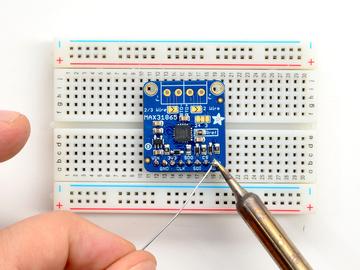
10 Prepare the header strip: Cut the strip to length if necessary. It will be easier to solder if you insert it into a breadboard - long pins down Solder! Be sure to solder all pins for reliable electrical contact. (For tips on soldering, be sure to check out our Guide to Excellent Soldering ( Adafruit Industries Page 10 of 30


11 Adafruit Industries Page 11 of 30


12 Next we will solder in the two 3.5mm terminal blocks used to connect power & the motor to the breakout board. Make sure the open parts of the terminals face outwards so you can easily connect wires To make it easier to keep these in place, you can use some tape to hold down the two header pieces. Tacky clay also works, whatever you've got handy! Adafruit Industries Page 12 of 30


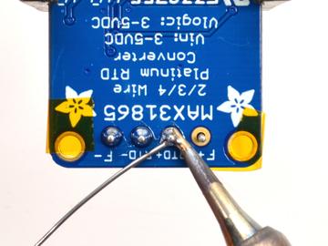
13 Solder in both pins of each terminal block. You can remove the tape when done. Adafruit Industries Page 13 of 30


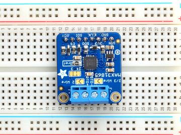
14 OK You're done! Adafruit Industries Page 14 of 30

15 RTD Wiring & Config RTDs are really very simple devices: just a small strip of Platinum that measures 100Ω or 1000Ω exactly at 0 C. Bonded to the PT100/PT1000 are 2, 3 or 4 wires. 4-Wire RTDs We'll explain the 4-wire version since that's the most complex. Normally if you want to measure a resistor you just connect your multimeter to each side of the resistor. The multimeter puts a small current through the resistor and measures the voltage generated across it (remember V = I * R). This works great for just about all resistors. However, for very precise readings of low-resistance resistors, you also have to account for the wires connected! For basic resistors, they are only good to 5% anyways so we don't mind the resistance of the wires. For RTDs, the wires, especially the 1 meter long ones, are 1, 2 maybe even 4Ω of extra resistance! That can add up to half or even a full C! No good, we want to make sure that resistance is not included in our measurement Thus, the 4-wire RTD. Each side of the RTD has two wires attached. Each wire is maybe 1Ω of resistance. When connected to the amplifier, the smart amp will measure the voltage across the RTD and also across the wire pairs. For example, here's the approximate resistances of a 4-Wire PT100 RTD at 0 C (for a PT1000, the middle resistance would be (1002Ω rather than 102Ω) (Remember that the middle resistance or 1002 Ω - will vary with temperature, but the 2Ω wires will not) When the amp measures this sensor, it will measure the resistance between one set of red and blue wires. It will then measure the resistances between the red wires and blue wires. Then divide those resistances by half - since there's two wires and we just want the resistance of one wire. The final result is = 100Ω 3-Wire RTDs Adafruit Industries Page 15 of 30

16 These are very similar to the 4-wire type but there is only one 'pair' of connected wires. The reasoning for this is that the wires for the RTD are all pretty much the same gauge and length, so rather than having two pairs, the amplifier will just read one pair and use that resistance as the same for both wires. 2-Wire RTDs These are as simple as it gets, only one wire per side. You may need to calibrate the sensor by putting it in an ice bath to get the resistance at 0 C (say 102Ω) and then subtracting 100Ω to figure out the collective resistance of the connection wires! Adafruit Industries Page 16 of 30
 and which connect through the RTD. Chances are the wires that connect together are the same color.")
17 How To Wire Up! 4-Wire Sensors Connect the four wires to each of the pads. Use a multimeter to determine which wires connect together directly (2 ohms or so between them) and which connect through the RTD. Chances are the wires that connect together are the same color. The two pairs connect so that the ones that are connected together go into the two matching terminal blocks on left or right. It doesn't matter which of the matched pair is on the outside or inside. It doesn't matter which of the match pairs are on the left or right. Do not solder closed any jumpers or cut any jumpers. Use as is! Adafruit Industries Page 17 of 30
18 3-Wire Sensors Connect the three wires to the three right-most contacts. Use a multimeter to determine which wires connect together directly (2 ohms or so between them) and which connect through the RTD. Chances are the wires that connect together are the same color. The two wires that are connected together should go in the right-most blocks (labeled F+ and RTD+). It doesn't matter which of the matched pair is on the outside or inside. The third wire that is on the other side of the RTD connects to the left (marked F- or RTD-). It doesn't matter which slot it's in! Adafruit Industries Page 18 of 30

19 You will have to cut the thin trace in between the 2-way jumper on the right side of the board, and then solder closed the blob on the right side. Then next to the terminal block on the left, solder closed that jumper as well. Alternatively you can put a piece of wire into the terminal blocks to 'short' them 2 Wire Sensor This is the easiest wiring, you can just use either terminal block slot on the sides for each wire. Then either solder closed the jumpers next to the RTD terminal block or put little wires in the right and left terminal blocks to short them together. Adafruit Industries Page 19 of 30

20 Arduino Code You can easily wire this breakout to any microcontroller, we'll be using an Arduino. For another kind of microcontroller, as long as you have 4 available pins it is possible to 'bit-bang SPI' or you can use hardware SPI if you like. Just check out the library, then port the code. SPI Wiring Since this is a SPI-capable sensor, we can use hardware or 'software' SPI. To make wiring identical on all Arduinos, we'll begin with 'software' SPI. The following pins should be used: Connect Vin to the power supply, 3V or 5V is fine. Use the same voltage that the microcontroller logic is based off of. For most Arduinos, that is 5V Connect GND to common power/data ground Connect the SCK pin to Digital #13 but any pin can be used later Connect the SDO pin to Digital #12 but any pin can be used later Connect the SDI pin to Digital #11 but any pin can be used later Connect the CS pin Digital #10 but any pin can be used later Later on, once we get it working, we can adjust the library to use hardware SPI if you desire, or change the pins to other Download Adafruit_MAX31865 library To begin reading sensor data, you will need to download Adafruit_MAX31865 from our github repository. You can do that by visiting the github repo and manually downloading or, easier, just click this button to download the zip Download latest Adafruit MAX31865 Arduino Adafruit Industries Page 20 of 30

21 Library Rename the uncompressed folder Adafruit_MAX31865 and check that the Adafruit_MAX31865 folder contains Adafruit_MAX31865.cpp and Adafruit_MAX31865.h Place the Adafruit_MAX31865 library folder your arduinosketchfolder/libraries/ folder. You may need to create the libraries subfolder if its your first library. Restart the IDE. We also have a great tutorial on Arduino library installation at: Restart the IDE Attach PT100 or PT1000 RTD You'll need to attach an RTD, for this demo we'll be using a 3-wire 1 meter long one but you can adjust the demo if you have a 2 or 4 wire. Check the RTD wiring page for the jumpers and wiring requirements! Load Demo Open up File->Examples->Adafruit_MAX31865->max31865 and upload to your Arduino wired up to the sensor. Adjust the max.begin(max31865_3wire) line if necessary. Adafruit Industries Page 21 of 30

 You can use that ratio to calculate the resistance and then determine the temperature Adafruit Industries https://learn.")
22 Upload to your Arduino and open up the serial console at baud to see a print out of the sensors data. The MAX31865 doesn't actually return the resistance it measures. Instead it returns the ratio between the resistance measured and the Rref reference resistor. For the PT100 version of the breakout, this is a 430 ohm 0.1% resistor (marking is 4300!!!) For the PT100 version of the breakout, this is a 4300 ohm 0.1% resistor (marking is 4301!!!) You can use that ratio to calculate the resistance and then determine the temperature Adafruit Industries Page 22 of 30
23 More Accuracy Our library is efficient and small and uses an algorithm to calculate temperature. While this works very well, it isn't as accurate as it could be. Check out this ITS-90 conforming library from DrHaney that uses a lookup table for better accuracy! Library Reference You can start out by creating a MAX31865 object with either software SPI (where all four pins can be any I/O) using // Use software SPI: CS, DI, DO, CLK Adafruit_MAX31865 max = Adafruit_MAX31865(10, 11, 12, 13); Or you can use hardware SPI. With hardware SPI you must use the hardware SPI pins for your Arduino - and each arduino type has different pins! Check the SPI reference to see what pins to use. In this case, you can use any CS pin, but the other three pins are fixed // use hardware SPI, just pass in the CS pin Adafruit_MAX31865 max = Adafruit_MAX31865(10); Once started, you can initialize the sensor with one of the following, depending on what kind of RTD you've got connected! max.begin(max31865_2wire) max.begin(max31865_3wire) max.begin(max31865_4wire) Reading Resistance If you want to know the actual resistance (not temperature) you can do that fairly easily. You can read ratio from the MAX31865 with max.readrtd() This will give you the raw 16-bit unsigned value where 0xFFFF is '1.0 ratio'. Chances are you want to convert it to the resistance. We recommend this code: Serial.print("RTD value: "); Serial.println(rtd); float ratio = rtd; ratio /= 32768; Serial.print("Ratio = "); Serial.println(ratio,8); Serial.print("Resistance = "); Serial.println(RREF*ratio,8); You'll need to define RREF - in this case its for PT100 and for PT1000 Calculating Temperature Once you have the resistance you can look up in an RTD table or use a calculation to do a best-fit approximation. We use the example from this app note: Adafruit Industries Page 23 of 30
24 notes/an709_0.pdf It's fast and seems to work very well! We have a one-stop function that does everything for you, just call: max.temperature(100, RREF) Where the first argument is the resistance of the RTD at 0 C (for PT100 that's 100) and the second argument is the value of the reference resistor. This function returns the tempreature in C Faults The MAX31865 has a wide-ranging fault mechanism that can alert you via pin or function when something is amiss. Don't forget to test this functionality before relying on it! You can read faults with max.readfault() Which will return a uint8_t type with bits set for each of 6 different fault types. You can test for each one with this set of code: // Check and print any faults uint8_t fault = max.readfault(); if (fault) { Serial.print("Fault 0x"); Serial.println(fault, HEX); if (fault & MAX31865_FAULT_HIGHTHRESH) { Serial.println("RTD High Threshold"); } if (fault & MAX31865_FAULT_LOWTHRESH) { Serial.println("RTD Low Threshold"); } if (fault & MAX31865_FAULT_REFINLOW) { Serial.println("REFIN- > 0.85 x Bias"); } if (fault & MAX31865_FAULT_REFINHIGH) { Serial.println("REFIN- < 0.85 x Bias - FORCE- open"); } if (fault & MAX31865_FAULT_RTDINLOW) { Serial.println("RTDIN- < 0.85 x Bias - FORCE- open"); } if (fault & MAX31865_FAULT_OVUV) { Serial.println("Under/Over voltage"); } max.clearfault(); } In particular, the last four are ones that indicate a hardware failure. The first two are threshold faults, we don't have code for setting those thresholds at this time. Adafruit Industries Page 24 of 30

25 CircuitPython Code It's easy to use the MAX31865 sensor with CircuitPython and the Adafruit CircuitPython MAX31865 module. This module allows you to easily write Python code that reads the range from the sensor. First wire up a MAX31865 to your board exactly as shown on the previous pages for Arduino. Here's an example of wiring a Feather M0 to the sensor with a SPI connection: Board 3V to sensor VIN Board GND to sensor GND Board SCK to sensor CLK Board MOSI to sensor SDI Board MISO to sensor SDO Board D5 to sensor CS (or any other digital I/O pin) Next you'll need to install the Adafruit CircuitPython MAX31865 library on your CircuitPython board. Remember this module is for Adafruit CircuitPython firmware and not MicroPython.org firmware! First make sure you are running the latest version of Adafruit CircuitPython for your board. Next you'll need to install the necessary libraries to use the hardware--carefully follow the steps to find and install these libraries from Adafruit's CircuitPython library bundle. For example the Circuit Playground Express guide has a great page on how to install the library bundle for both express and non-express boards. Remember for non-express boards like the Trinket M0, Gemma M0, and Feather/Metro M0 basic you'll need to manually install the necessary libraries from the bundle: adafruit_max31865.mpy adafruit_bus_device Adafruit Industries Page 25 of 30
26 You can also download the adafruit_max31865.mpy from its releases page on Github. Before continuing make sure your board's lib folder or root filesystem has the adafruit_max31865.mpy, and adafruit_bus_device files and folders copied over. Next connect to the board's serial REPL so you are at the CircuitPython >>> prompt. Usage To demonstrate the usage of the sensor we'll initialize it and read the range and more from the board's Python REPL. Run the following code to import the necessary modules and initialize the SPI connection with the sensor: import board import busio import digitalio import adafruit_max31865 spi = busio.spi(board.sck, MOSI=board.MOSI, MISO=board.MISO) cs = digitalio.digitalinout(board.d5) # Chip select of the MAX31865 board. sensor = adafruit_max31865.max31865(spi, cs) Notice you need to explicitly define the chip select digital I/O pin--be sure to use the same pin as your wiring (D5 if following this example exactly). By default the MAX31865 class assumes a 2 wire sensor, however you can change this by setting the wires keyword argument in the initializer. Set this to the number of wires in your sensor (2, 3, or 4). For example to create a 3 wire sensor: import board import busio import digitalio import adafruit_max31865 spi = busio.spi(board.sck, MOSI=board.MOSI, MISO=board.MISO) cs = digitalio.digitalinout(board.d5) # Chip select of the MAX31865 board. sensor = adafruit_max31865.max31865(spi, cs, wires=3) Be sure to set wires to the appropriate value for your sensor! In addition you can specify the nominal resistance and reference resistance of the RTD with these optional keyword arguments of the initializer: rtd_nominal - This is the resistance value in Ohms of the RTD at a nominal value (typically 0 degrees Celsius). This defaults to 100 for a PT100 sensor. For a PT1000 change it to 1000 Ohms. ref_resistor - The reference resistor value in Ohms. The default is 430 Ohms which matches the PT100 version of the breakout. For a PT1000 breakout change this to 4300 Ohms. For example here's how to create a 2-wire PT1000 sensor instance with 1000 Ohm nominal resistance and 4300 Ohm reference resistance: Adafruit Industries Page 26 of 30
27 import board import busio import digitalio import adafruit_max31865 spi = busio.spi(board.sck, MOSI=board.MOSI, MISO=board.MISO) cs = digitalio.digitalinout(board.d5) # Chip select of the MAX31865 board. sensor = adafruit_max31865.max31865(spi, cs, rtd_nominal=1000.0, ref_resistor=4300.0) Now you're ready to read values from the sensor using any of these properties: temperature - The temperature measured by the sensor in degrees Celsius. resistance - The resistance of the RTD in Ohms. print('temperature: {0:0.3f}C'.format(sensor.temperature)) print('resistance: {0:0.3f} Ohms'.format(sensor.resistance)) See the simpletest.py example for a complete demo of printing the range every second. Save this as main.py on the board and examine the REPL output to see the temperature printed every second. # Simple demo of the MAX31865 thermocouple amplifier. # Will print the temperature every second. import time import board import busio import digitalio import adafruit_max31865 # Initialize SPI bus and sensor. spi = busio.spi(board.sck, MOSI=board.MOSI, MISO=board.MISO) cs = digitalio.digitalinout(board.d5) # Chip select of the MAX31865 board. sensor = adafruit_max31865.max31865(spi, cs) # Note you can optionally provide the thermocouple RTD nominal, the reference # resistance, and the number of wires for the sensor (2 the default, 3, or 4) # with keyword args: #sensor = adafruit_max31865.max31865(spi, cs, rtd_nominal=100, ref_resistor=430.0, wires=2) # Main loop to print the temperature every second. while True: # Read temperature. temp = sensor.temperature # Print the value. print('temperature: {0:0.3f}C'.format(temp)) # Delay for a second. time.sleep(1.0) That's all there is to using the MAX31865 with CircuitPython! Adafruit Industries Page 27 of 30
28 Adafruit Industries Page 28 of 30
29 Downloads Files Fritzing object in Adafruit Fritzing library EagleCAD PCB files on GitHub Library on GitHub MAX31865 Datasheet A "lookup table" based library is bigger but more precise since it doesn't do an approximation of the temperature - for advanced users! Schematic & Fabrication Print Adafruit Industries Page 29 of 30

30 Adafruit Industries Last Updated: :12:18 PM UTC Page 30 of 30
Adafruit MCP9808 Precision I2C Temperature Sensor Guide
 Adafruit MCP9808 Precision I2C Temperature Sensor Guide Created by lady ada Last updated on 2017-11-12 06:09:49 PM UTC Guide Contents Guide Contents Overview Pinouts Power Pins I2C Data Pins Optional Pins
Adafruit Si7021 Temperature + Humidity Sensor
 Adafruit Si7021 Temperature + Humidity Sensor Created by lady ada Last updated on 2017-11-12 06:14:07 PM UTC Guide Contents Guide Contents Overview Pinouts Power Pins: I2C Logic pins: Assembly Prepare
Adafruit VL53L0X Time of Flight Micro-LIDAR Distance Sensor Breakout
 Adafruit VL53L0X Time of Flight Micro-LIDAR Distance Sensor Breakout Created by lady ada Last updated on 2017-12-28 11:56:14 PM UTC Guide Contents Guide Contents Overview Sensing Capablities Pinouts Power
Adafruit APDS9960 breakout
 Adafruit APDS9960 breakout Created by Dean Miller Last updated on 2018-01-19 11:18:59 PM UTC Guide Contents Guide Contents Overview Pinouts Power Pins: Logic pins: Assembly Prepare the header strip: Add
Adafruit AM2320 Sensor
 Adafruit AM2320 Sensor Created by lady ada Last updated on 2018-03-07 09:49:28 PM UTC Guide Contents Guide Contents Overview Pinouts Arduino Usage Install Adafruit Sensor Download Adafruit_AM2320 Load
Adafruit DRV2605 Haptic Controller Breakout
 Adafruit DRV2605 Haptic Controller Breakout Created by lady ada Last updated on 2018-08-20 03:28:51 PM UTC Guide Contents Guide Contents Overview Pinouts Power Pins I2C Pins Other! Assembly Prepare the
MCP Bit DAC Tutorial
 MCP4725 12-Bit DAC Tutorial Created by lady ada Last updated on 2018-03-05 10:51:16 PM UTC Guide Contents Guide Contents Overview Wiring Arduino Code Using the library Increasing the speed CircuitPython
Adafruit MMA8451 Accelerometer Breakout
 Adafruit MMA8451 Accelerometer Breakout Created by lady ada Last updated on 2018-02-06 04:55:03 PM UTC Guide Contents Guide Contents Overview Pinouts Power Pins I2C Pins INT and ADDR Pins Assembly Prepare
Adafruit CCS811 Air Quality Sensor
 Adafruit CCS811 Air Quality Sensor Created by Dean Miller Last updated on 2018-01-15 11:03:58 PM UTC Guide Contents Guide Contents Overview Pinouts Power Pins: Logic pins: Arduino Wiring & Test I2C Wiring
Adafruit SGP30 TVOC/eCO2 Gas Sensor
 Adafruit SGP30 TVOC/eCO2 Gas Sensor Created by lady ada Last updated on 2018-03-06 12:33:17 AM UTC Guide Contents Guide Contents Overview Pinouts Power Pins: Data Pins Wiring Parts Wiring Arduino Code
Adafruit MMA8451 Accelerometer Breakout
 Adafruit MMA8451 Accelerometer Breakout Created by lady ada Last updated on 2014-07-31 07:00:14 PM EDT Guide Contents Guide Contents Overview Pinouts (http://adafru.it/dln)power Pins I2C Pins INT and ADDR
Adafruit AS channel Visible Light Sensor
 Adafruit AS7262 6-channel Visible Light Sensor Created by Dean Miller Last updated on 2018-03-28 08:29:27 PM UTC Guide Contents Guide Contents Overview Pinouts Power Pins: Logic pins: UART Logic pins:
Adafruit Color Sensors
 Adafruit Color Sensors Created by Bill Earl Last updated on 2018-11-05 03:48:12 PM UTC Guide Contents Guide Contents Overview Assembly and Wiring Assembly (breakout version only) Position the header Position
Adafruit Si5351 Clock Generator Breakout
 Adafruit Si5351 Clock Generator Breakout Created by lady ada Last updated on 2017-06-02 07:54:50 PM UTC Guide Contents Guide Contents Overview Pinouts Power Pins I2C Pins Assembly Prepare the header strip:
Adafruit DRV2605 Haptic Controller Breakout
 Adafruit DRV2605 Haptic Controller Breakout Created by lady ada Last updated on 2016-10-03 09:48:16 PM UTC Guide Contents Guide Contents Overview Pinouts Power Pins I2C Pins Other! Assembly Prepare the
Adafruit I2C FRAM Breakout
 Adafruit I2C FRAM Breakout Created by lady ada Last updated on 2017-07-14 05:38:45 AM UTC Guide Contents Guide Contents Overview Pinouts Power Pins: I2C Logic pins: Assembly Prepare the header strip: Add
TSL2561 Luminosity Sensor
 TSL2561 Luminosity Sensor Created by lady ada Last updated on 2018-01-27 12:17:52 AM UTC Guide Contents Guide Contents Overview Wiring the TSL2561 Sensor Breakout Board Prep Wiring up the sensor Arduino
Adafruit AMG8833 8x8 Thermal Camera Sensor
 Adafruit AMG8833 8x8 Thermal Camera Sensor Created by Justin Cooper Last updated on 2017-11-27 10:00:27 PM UTC Guide Contents Guide Contents Overview Pinouts Power Pins: Logic pins: Assembly Prepare the
Monochrome OLED Breakouts
 Monochrome OLED Breakouts Created by lady ada Last updated on 2018-01-02 08:35:47 PM UTC Guide Contents Guide Contents Overview Power Requirements OLED Power Requirements 5V- ready 128x64 and 128x32 OLEDs
Adafruit 7-Segment LED FeatherWings
 Adafruit 7-Segment LED FeatherWings Created by lady ada Last updated on 2017-11-26 08:48:20 PM UTC Guide Contents Guide Contents Overview Pinouts Power Pins I2C pins Address Jumpers Changing Addresses
Adafruit MMA8451 Accelerometer Breakout
 Adafruit MMA8451 Accelerometer Breakout Created by lady ada Last updated on 2018-08-22 03:42:52 PM UTC Guide Contents Guide Contents Overview Pinouts (https://adafru.it/dln)power Pins I2C Pins INT and
Adafruit MPRLS Ported Pressure Sensor Breakout
 Adafruit MPRLS Ported Pressure Sensor Breakout Created by lady ada Last updated on 2018-09-26 08:51:24 PM UTC Guide Contents Guide Contents Overview Pinouts Power Pins: I2C Logic pins: Other pins: Arduino
Adafruit 1.27" and 1.5" Color OLED Breakout Board
 Adafruit 1.27" and 1.5" Color OLED Breakout Board Created by Bill Earl Last updated on 2017-11-17 05:54:22 PM UTC Guide Contents Guide Contents Overview Board Technical Details Assembly Prepare the header
Adafruit 8x16 LED Matrix FeatherWing
 Adafruit 8x16 LED Matrix FeatherWing Created by lady ada Last updated on 2019-01-28 05:47:44 PM UTC Guide Contents Guide Contents Overview Pinouts Power Pins I2C pins Address Jumpers Changing Addresses
Adafruit Mini TFT " 160x80
 Adafruit Mini TFT - 0.96" 160x80 Created by lady ada Last updated on 2017-11-17 05:56:10 PM UTC Guide Contents Guide Contents Overview Pinouts Assembly Prepare the header strip: Add the breakout board:
i2c/spi LCD Backpack Created by lady ada Last updated on :11:04 PM UTC
 i2c/spi LCD Backpack Created by lady ada Last updated on 2017-08-16 05:11:04 PM UTC Guide Contents Guide Contents Overview Which LCD to Use? Wait - the backpack has 16 holes, but my LCD only has 14 pins!
Adafruit 8x16 LED Matrix FeatherWing
 Adafruit 8x16 LED Matrix FeatherWing Created by lady ada Last updated on 2016-05-20 01:58:38 PM EDT Guide Contents Guide Contents Overview Pinouts Power Pins I2C pins Address Jumpers Changing Addresses
Adafruit LIS3DH Triple-Axis Accelerometer Breakout
 Adafruit LIS3DH Triple-Axis Accelerometer Breakout Created by lady ada Last updated on 2017-11-14 02:21:20 AM UTC Guide Contents Guide Contents Overview Pinouts Power Pins I2C Pins SPI pins: Other Pins
IS31FL x9 Charlieplexed PWM LED Driver
 IS31FL3731 16x9 Charlieplexed PWM LED Driver Created by lady ada Last updated on 2018-01-10 06:31:05 PM UTC Guide Contents Guide Contents Overview Pinouts Power Pins I2C Data Pins Other Control Pins LED
Adafruit ATWINC1500 WiFi Breakout
 Adafruit ATWINC1500 WiFi Breakout Created by lady ada Last updated on 2018-01-29 08:25:04 PM UTC Guide Contents Guide Contents Overview Pinouts Power Pins SPI Pins Other SPI Interface Pins Assembly Prepare
Adafruit DS3231 Precision RTC Breakout
 Adafruit DS3231 Precision RTC Breakout Created by lady ada Last updated on 2017-11-26 10:28:38 PM UTC Guide Contents Guide Contents Overview Pinouts Power Pins: I2C Logic pins: Other Pins: Assembly Prepare
14-Segment Alpha-numeric LED FeatherWing
 14-Segment Alpha-numeric LED FeatherWing Created by lady ada Last updated on 2017-11-26 08:54:28 PM UTC Guide Contents Guide Contents Overview Pinouts Power Pins I2C pins Address Jumpers Changing Addresses
Joy Featherwing. Created by Dean Miller. Last updated on :03:07 PM UTC
 Joy Featherwing Created by Dean Miller Last updated on 2018-08-22 04:03:07 PM UTC Guide Contents Guide Contents Overview Pinouts Power and Reset Pins I2C Data Pins I2C Addressing Optional Interrupt Pin
MCP Bit DAC Tutorial
 MCP4725 12-Bit DAC Tutorial Created by lady ada Last updated on 2016-10-07 04:47:03 PM UTC Guide Contents Guide Contents Overview Wiring Using with Arduino Using the library Increasing the speed Download
Adafruit GPIO Expander Bonnet for Raspberry Pi Created by Kattni Rembor. Last updated on :12:47 PM UTC
 Adafruit GPIO Expander Bonnet for Raspberry Pi Created by Kattni Rembor Last updated on 2019-03-09 11:12:47 PM UTC Overview The Raspberry Pi is an amazing single board computer - and one of the best parts
Adafruit Capacitive Touch Sensor Breakouts
 Adafruit Capacitive Touch Sensor Breakouts Created by Bill Earl Last updated on 2018-08-22 03:36:13 PM UTC Guide Contents Guide Contents Overview Momentary Toggle 5-Pad Momentary Assembly and Wiring Installing
0.96" mini Color OLED
 0.96" mini Color OLED Created by lady ada Last updated on 2016-09-08 03:41:52 PM UTC Guide Contents Guide Contents Overview Power Wiring New Model Older Model Wiring the OLDER design (two rows of pins
Adafruit eink Display Breakouts
 Adafruit eink Display Breakouts Created by lady ada Last updated on 2018-07-18 07:24:25 PM UTC Guide Contents Guide Contents Overview Pinouts Power Pins Data Control Pins Usage & Expectations Arduino Code
Adafruit PCF8523 Real Time Clock
 Adafruit PCF8523 Real Time Clock Created by lady ada Last updated on 2017-12-29 06:07:09 AM UTC Guide Contents Guide Contents Overview Pinouts Power Pins: I2C Logic pins: Other Pins: Assembly Prepare the
Adafruit TPL5110 Power Timer Breakout
 Adafruit TPL5110 Power Timer Breakout Created by lady ada Last updated on 2017-12-11 06:28:19 AM UTC Guide Contents Guide Contents Overview Pinouts Power Pins Control Pins Assembly Prepare the header strip:
Adafruit ATWINC1500 WiFi Breakout
 Adafruit ATWINC1500 WiFi Breakout Created by lady ada Last updated on 2016-03-09 12:29:56 PM EST Guide Contents Guide Contents Overview Pinouts Power Pins SPI Pins Other SPI Interface Pins Assembly Prepare
Adafruit TPL5111 Reset Enable Timer Breakout
 Adafruit TPL5111 Reset Enable Timer Breakout Created by lady ada Last updated on 2017-11-02 07:32:27 PM UTC Guide Contents Guide Contents Overview Pinouts Power Pins Control Pins Assembly Prepare the header
1.8" TFT Display Breakout and Shield
 1.8" TFT Display Breakout and Shield Created by lady ada Last updated on 2017-11-17 05:51:22 PM UTC Guide Contents Guide Contents Overview Breakout Pinouts Breakout Assembly Prepare the header strip: Add
Adafruit ATWINC1500 WiFi Breakout
 Adafruit ATWINC1500 WiFi Breakout Created by lady ada Last updated on 2016-09-22 07:01:05 PM UTC Guide Contents Guide Contents Overview Pinouts Power Pins SPI Pins Other SPI Interface Pins Assembly Prepare
Adafruit WINC1500 WiFi Shield for Arduino
 Adafruit WINC1500 WiFi Shield for Arduino Created by lady ada Last updated on 2017-11-27 07:04:37 PM UTC Guide Contents Guide Contents Overview Pinouts SPI Interface Pins WiFi Control Pins SD Card Interface
MLX90393 Wide-Range 3-Axis Magnetometer
 MLX90393 Wide-Range 3-Axis Magnetometer Created by Kevin Townsend Last updated on 2019-02-15 01:48:36 AM UTC Guide Contents Guide Contents Overview Specifications Pinout Power Pins Digital Pins Arduino
Introducing Adafruit Trellis
 Introducing Adafruit Trellis Created by lady ada Last updated on 2016-09-16 09:12:22 PM UTC Guide Contents Guide Contents Overview Adding LEDs Connecting Library reference Creating the objects Controlling
Adafruit Mini TFT with Joystick Featherwing
 Adafruit Mini TFT with Joystick Featherwing Created by lady ada Last updated on 2018-08-24 04:45:05 AM UTC Guide Contents Guide Contents Overview Pinouts Color TFT Display Buttons and Joystick seesaw Chip
Neon LED Signs. Created by John Park. Last updated on :11:09 PM UTC
 Neon LED Signs Created by John Park Last updated on 2018-08-22 04:11:09 PM UTC Guide Contents Guide Contents Overview Parts Materials Tools Build the Sign Driver Preparation Solder the Circuit Solder the
Adafruit HUZZAH32 - ESP32 Feather
 Adafruit HUZZAH32 - ESP32 Feather Created by lady ada Last updated on 2017-07-14 02:14:00 AM UTC Guide Contents Guide Contents Overview Pinouts Power Pins Logic pins Serial pins I2C & SPI pins GPIO & Analog
Adafruit PowerBoost 500 Shield
 Adafruit PowerBoost 500 Shield Created by lady ada Last updated on 2018-08-22 03:43:27 PM UTC Guide Contents Guide Contents Overview Pinouts DC/DC Boost section Indicator LEDs Charging section Power Switch
Adafruit 2.4" TFT FeatherWing
 Adafruit 2.4" TFT FeatherWing Created by lady ada Last updated on 2018-01-12 04:29:29 PM UTC Guide Contents Guide Contents Overview Pinouts Power Pins SPI Pins TFT Control Pins Touch Screen control pins
Adafruit 3.5" 480x320 TFT FeatherWing
 Adafruit 3.5" 480x320 TFT FeatherWing Created by lady ada Last updated on 2017-10-29 06:25:16 PM UTC Guide Contents Guide Contents Overview Pinouts Power Pins SPI Pins Touch Screen control pins SD Card
Adafruit TSL2591 High Dynamic Range Digital Light Sensor
 Adafruit TSL2591 High Dynamic Range Digital Light Sensor Created by lady ada Last updated on 2018-01-27 05:10:53 PM UTC Guide Contents Guide Contents Overview Pinouts Power Pins: I2C Logic pins: Other
Adafruit LED Backpacks
 Adafruit LED Backpacks Created by lady ada Last updated on 2018-08-22 03:30:15 PM UTC Guide Contents Guide Contents Overview 1.2" 8x8 Matrix (https://adafru.it/apt)mini 8x8 Matrix Software 0.8" 8x8 Matrix
Adafruit 3.5" 480x320 TFT FeatherWing
 Adafruit 3.5" 480x320 TFT FeatherWing Created by lady ada Last updated on 2018-06-17 10:09:34 PM UTC Guide Contents Guide Contents Overview Pinouts Power Pins SPI Pins Touch Screen control pins SD Card
Introducing Circuit Playground
 Introducing Circuit Playground Created by lady ada Last updated on 2016-08-27 02:46:58 AM UTC Guide Contents Guide Contents Overview Pinouts GPIO + Capacitive Touch Pads NeoPixels Pushbuttons Slide Switch
Sino:bit with Arduino
 Sino:bit with Arduino Created by Dave Astels Last updated on 2017-12-04 02:22:05 PM UTC Guide Contents Guide Contents Accelerometer and Magnetometer Magnetometer Accelerometer Adafruit Libraries Download
RGB LCD Shield. Created by lady ada. Last updated on :48:40 PM UTC
 RGB LCD Shield Created by lady ada Last updated on 2017-12-04 11:48:40 PM UTC Guide Contents Guide Contents Overview Parts List 1) Resistors 2) Potentiometer 3) Pushbuttons 4) i2c Port Expander Chip 5)
Data Logging with Feather and CircuitPython
 Data Logging with Feather and CircuitPython Created by Kattni Rembor Last updated on 2018-04-30 09:58:20 PM UTC Guide Contents Guide Contents Overview Things You'll Need Adafruit Feather M0 Express - Designed
Flora Wearable GPS. Created by Becky Stern. Last updated on :32:36 PM UTC
 Flora Wearable GPS Created by Becky Stern Last updated on 2018-08-22 03:32:36 PM UTC Guide Contents Guide Contents Overview Hook up GPS Program FLORA Basic Echo Test Install Adafruit GPS Library Load Echo
Introducing Circuit Playground
 Introducing Circuit Playground Created by lady ada Last updated on 2016-11-03 08:53:06 AM UTC Guide Contents Guide Contents Overview Pinouts GPIO + Capacitive Touch Pads NeoPixels Pushbuttons Slide Switch
Adafruit LED Backpacks
 Adafruit LED Backpacks Created by lady ada Last updated on 2017-09-08 07:40:11 PM UTC Guide Contents Guide Contents Overview 1.2" 8x8 Matrix (http://adafru.it/apt)mini 8x8 Matrix Software 0.8" 8x8 Matrix
Circuit Playground Digital Input
 Circuit Playground Digital Input Created by Carter Nelson Last updated on 2017-02-27 03:36:50 AM UTC Guide Contents Guide Contents Overview Required Parts Before Starting Digital Signals 3V Logic Pocket
Android GBoard Morse Code Control with Circuit Playground Express
 Android GBoard Morse Code Control with Circuit Playground Express Created by Dave Astels Last updated on 2018-08-22 04:10:30 PM UTC Guide Contents Guide Contents Overview Parts Materials for the box Installing
Getting Started with FLORA
 Getting Started with FLORA Created by Becky Stern Last updated on 2018-01-03 04:31:24 AM UTC Guide Contents Guide Contents Overview Windows Driver Installation Manual Driver Installation Download software
FeatherWing Proto, Doubler and Tripler
 FeatherWing Proto, Doubler and Tripler Created by lady ada Last updated on 2018-11-15 10:39:12 PM UTC Guide Contents Guide Contents Overview FeatherWing Proto FeatherWing Doubler FeatherWing Tripler Proto
NeoMatrix 8x8 Word Clock
 NeoMatrix 8x8 Word Clock Created by Andy Doro Last updated on 2017-10-10 04:10:51 AM UTC Guide Contents Guide Contents Overview Parts List Parts Tools Circuit Assembly Overview Uploading Code Understanding
Adafruit Prototyping Pi Plate. Created by Ladyada
 Adafruit Prototyping Pi Plate Created by Ladyada Guide Contents Guide Contents Overview Solder it! User Manual Buy Adafruit Prototyping Pi Plate 2 3 4 14 17 Adafruit Industries http://learn.adafruit.com/adafruit-prototyping-pi-plate
FeatherWing Proto and Doubler
 FeatherWing Proto and Doubler Created by lady ada Last updated on 2016-09-19 05:11:36 PM UTC Guide Contents Guide Contents Overview FeatherWing Proto FeatherWing Doubler Proto Pinout Proto Pinout Duplicated
MiniPOV4 - DIY Full-Color Persistence of Vision & Light-Painting Kit
 MiniPOV4 - DIY Full-Color Persistence of Vision & Light-Painting Kit Created by lady ada Last updated on 2018-08-22 03:41:06 PM UTC Guide Contents Guide Contents Overview Make it! Testing Upload Images
Adafruit Pi Cobbler Kit
 Adafruit Pi Cobbler Kit Created by lady ada Last updated on 2018-08-22 03:30:27 PM UTC Guide Contents Guide Contents Overview Solder it! Buy a Pi Cobbler Kit! Downloads 2 3 5 15 16 Adafruit Industries
Adafruit Feather 32u4 Basic Proto
 Adafruit Feather 32u4 Basic Proto Created by lady ada Last updated on 2016-09-21 01:21:46 AM UTC Guide Contents Guide Contents Overview Pinouts Power Pins Logic pins Other Pins! Assembly Header Options!
PyPortal NeoPixel Color Picker Created by Kattni Rembor. Last updated on :42:41 PM UTC
 PyPortal NeoPixel Color Picker Created by Kattni Rembor Last updated on 2019-03-27 10:42:41 PM UTC Overview This simple project adds a little color to your life with CircuitPython, PyPortal and NeoPixels.
Adafruit 9-DOF IMU Breakout
 Adafruit 9-DOF IMU Breakout Created by Kevin Townsend Last updated on 2018-08-22 03:39:45 PM UTC Guide Contents Guide Contents Introduction Related Links Connecting It Up Basic Setup (5V Logic, Arduino
Adafruit IO Basics: Servo
 Adafruit IO Basics: Servo Created by Todd Treece Last updated on 2018-08-22 03:59:11 PM UTC Guide Contents Guide Contents Overview Adafruit IO Setup Creating the Servo Feed Adding the Slider Block Wiring
Trellis 3D Printed Enclosure
 Trellis 3D Printed Enclosure Created by Ruiz Brothers Last updated on 2018-08-22 03:39:07 PM UTC Guide Contents Guide Contents Overview Parts Tools & Supplies Modeling 123D Design Customize Measuring Parts
FLORA TV-B-Gone. Created by Becky Stern. Last updated on :32:57 PM UTC
 FLORA TV-B-Gone Created by Becky Stern Last updated on 2018-08-22 03:32:57 PM UTC Guide Contents Guide Contents Overview Parts Tutorials Transistors Resistors LEDs Pushbutton Program it Power Fabric pinwheel
PyPortal View Master Created by Ruiz Brothers. Last updated on :51:28 AM UTC
 PyPortal View Master Created by Ruiz Brothers Last updated on 2019-03-13 11:51:28 AM UTC Overview In this project we re building a view master inspired device using Adafruit s PyPortal. The eyepiece makes
Adafruit GPS Hat in Windows IoT Core
 Adafruit GPS Hat in Windows IoT Core Created by Rick Lesniak Last updated on 2017-01-01 08:17:19 PM UTC Guide Contents Guide Contents Overview Assembly GPSDemoApp Adafruit Class Library 2 3 4 6 13 Adafruit
Adafruit Stepper + DC Motor FeatherWing
 Adafruit Stepper + DC Motor FeatherWing Created by lady ada Last updated on 2018-01-10 11:40:55 PM UTC Guide Contents Guide Contents Overview Pinouts Motor Power Pins Motor Outputs Logic Power Pins I2C
Adafruit 10-DOF IMU Breakout
 Adafruit 10-DOF IMU Breakout Created by Kevin Townsend Last updated on 2018-08-22 03:38:43 PM UTC Guide Contents Guide Contents Introduction Related Links Connecting It Up Basic Setup (5V Logic, Arduino
NeoPixel Bike Light. Created by Ruiz Brothers. Last updated on :43:46 PM UTC
 NeoPixel Bike Light Created by Ruiz Brothers Last updated on 2018-11-15 07:43:46 PM UTC Guide Contents Guide Contents Overview 3D Printed Headlight Adafruit's Feather Platform Circuit Python Powered Parts
Adafruit LED Sequins. Created by Becky Stern. Last updated on :02:00 AM UTC
 Adafruit LED Sequins Created by Becky Stern Last updated on 2018-03-02 04:02:00 AM UTC Guide Contents Guide Contents Overview Sewing with conductive thread Circuit Diagram GEMMA sequin hat Arduino Code
Adafruit IO Basics: Analog Input
 Adafruit IO Basics: Analog Input Created by Todd Treece Last updated on 2018-08-22 03:47:38 PM UTC Guide Contents Guide Contents Overview Adafruit IO Setup Creating the Analog Feed Adding the Gauge Block
Naughty or Nice Machine
 Naughty or Nice Machine Created by Brian Corteil Last updated on 2018-08-22 03:45:31 PM UTC Guide Contents Guide Contents Overview It knows if you have been Naughty or Nice! Make It! Parts The Case The
3D Printed 20w Amplifier Box
 3D Printed 20w Amplifier Box Created by Ruiz Brothers Last updated on 2018-02-26 06:48:02 PM UTC Guide Contents Guide Contents Overview Prerequisite Guide Tools & Supplies Parts 3D Printing Print in your
Prophet 600 GliGli mod
 Prophet 600 GliGli mod Created by Collin Cunningham Last updated on 2018-08-22 04:04:56 PM UTC Guide Contents Guide Contents Overview What you'll need Program the Teensy++ Modify the Teensy++ Prep header
Adafruit IO Basics: Digital Output
 Adafruit IO Basics: Digital Output Created by Todd Treece Last updated on 2017-09-12 03:10:33 PM UTC Guide Contents Guide Contents Overview Adafruit IO Setup Creating the Digital Feed Adding the Toggle
Adafruit IO Basics: Digital Input
 Adafruit IO Basics: Digital Input Created by Todd Treece Last updated on 2017-07-14 11:49:29 PM UTC Guide Contents Guide Contents Overview Adafruit IO Setup Creating the Digital Feed Adding the Gauge Block
BLE Light Switch with Feather nrf52840 and Crickit
 BLE Light Switch with Feather nrf52840 and Crickit Created by John Park Last updated on 2019-02-15 07:06:19 PM UTC Guide Contents Guide Contents Overview Parts Adafruit Feather nrf52840 Express Adafruit
Adafruit Flora Bluefruit LE
 Adafruit Flora Bluefruit LE Created by lady ada Last updated on 2018-08-22 03:48:18 PM UTC Guide Contents Guide Contents Overview Get started fast with the Bluefruit App You can do a lot more too! Pinouts
NeoPixie Dust Bag with Circuit Playground Express
 NeoPixie Dust Bag with Circuit Playground Express Created by John Park Last updated on 2017-12-20 10:00:29 PM UTC Guide Contents Guide Contents Overview Code It Setup Animation Color Touch Variable Color
DIY Circuit Playground Shields
 DIY Circuit Playground Shields Created by Dave Astels Last updated on 2018-08-22 04:05:06 PM UTC Guide Contents Guide Contents Overview Small Alligator Clip Test Lead (set of 12) Small Alligator Clip to
Coffee Detonator: The TNT Plunger Grinder
 Coffee Detonator: The TNT Plunger Grinder Created by John Park Last updated on 2017-04-12 08:04:36 PM UTC Guide Contents Guide Contents Overview Materials Voltage Conversion AC/DC Voltage Divider Microcontroller
Adafruit IO Basics: Temperature & Humidity
 Adafruit IO Basics: Temperature & Humidity Created by Todd Treece Last updated on 2018-03-13 03:35:08 PM UTC Guide Contents Guide Contents Overview Adafruit IO Setup Creating the Feeds Adding the Line
Crickit Dancing Marionette Kit Created by Dano Wall. Last updated on :03:11 PM UTC
 Crickit Dancing Marionette Kit Created by Dano Wall Last updated on 2019-04-04 07:03:11 PM UTC Overview This project demonstrates how to build a robotic marionette that is controlled with four arcade-style
Adafruit IO Basics: ESP Arduino
 Adafruit IO Basics: ESP8266 + Arduino Created by Todd Treece Last updated on 2017-03-27 10:31:41 PM UTC Guide Contents Guide Contents Overview Adafruit Feather HUZZAH with ESP8266 WiFi Pros/Cons of the
Interactive Gift Box. Created by codingpro. Last updated on :47:40 AM UTC
 Interactive Gift Box Created by codingpro Last updated on 2018-01-10 01:47:40 AM UTC Guide Contents Guide Contents Overview Adafruit GEMMA M0 - Miniature wearable electronic platform Lithium Ion Polymer
Trash Panda. Created by Dano Wall. Last updated on :30:46 AM UTC
 Trash Panda Created by Dano Wall Last updated on 2018-06-06 02:30:46 AM UTC Guide Contents Guide Contents Overview Amazon's playful boxes We have the technology Other supplies you will need Create your