PiGRRL 2. Created by Ruiz Brothers. Last updated on :41:35 AM UTC
|
|
|
- Dinah Dalton
- 6 years ago
- Views:
Transcription

1 PiGRRL 2 Created by Ruiz Brothers Last updated on :41:35 AM UTC
2 Guide Contents Guide Contents Overview Raspberry Pi Retro Game Console Easier to build! Project Expectations Adafruit Parts Tools and Supplies Circuit Diagram Wired Connections 3D Printing Material Options Parts Dimensions Tap Screw Holes Test Fit Openings Finishing Parts Software Download & Burn RetroPie Setup RetroPie Install PiTFT (fbcp) Support Installing Keypress (retrogame) support Uploading ROMs Exiting ROMs Remapping Controls Testing Controls Default Controls Gamepad PiGRRL Gamepad Design PiGRRL Gamepad PCB Install IC Box Header Solder IC Box Header Prep 6mm Tactile Buttons Install 6mm Tactile Buttons Solder Buttons to Gamepad PCB Soldered Gamepad PCB Tap Gamepad PCB Mounting Holes PiTFT Display GPIO #18 - LED Backlighting Cut Trace #18 PiCable PiCable Resizing Measure, Mark and Cut Ribbon Cable Cut Cable Removing Connector Peel Cable from Connector Install Connector to Shortened Ribbon Cable Adafruit Industries Page 2 of 86
3 Mash Top Piece to Connector Shortened Pi Ribbon Cable Amp & Speaker Prep PAM8302 Amp Measure Wires for Amp and Speaker Strip and Tin Wires Connect Wires to Speaker Connect Wires to Amp Power Circuit Prep PowerBoost 1000C Measure Wires for PowerBoost and Amp Connect Amp to PowerBoost 1000C Connected Amp, Speaker and PowerBoost 1000C Test fit Power Switch Prep Slide Switch Connect Wires to Switch Connect Switch to PowerBoost 1000C Wired Power Circuit Pi Audio Prep Wires for Rasp Pi Audio Prep Raspberry Pi Audio Pins Connect Wires to Raspberry Pi Connect Wires to Amp Shoulder Buttons Prep 12mm Tactile Buttons Prep Wires for Shoulder Buttons Connect Wires to Buttons Shoulder Buttons Final Connections Prep Wires for Gamepad PCB Prep Power Pins on Gamepad PCB Connect Shoulder Buttons to Gamepad PCB Connect Gamepad PCB to PowerBoost 1000C Final Wired Components Test Components Mount Components Install 2.8" PiTFT Install Gamepad PCB Connect Pi Cable Connected PiTFT and Gamepad Install Speaker Shoulder Button Mount Shoulder Button (cont.) Install Shoulder Button Mount Install Switch Install Raspberry Pi 2 Mount PowerBoost 1000C Mount Amp Test PowerBoost Circuit Install Lipo Battery Adafruit Industries Page 3 of 86
4 Almost Done! 74 Close It Up! 75 Join Parts 75 Screw Bottom Portion 76 Insert microsd Card 77 Completed Build! 77 Share Your Creation With Us! 77 Trouble Shooting 78 Buttons don't work, things are very weird 78 Audio Issues 78 No Audio 79 Pressing Button Turns Off Screen 79 Button on pin #18 doesn't work 79 PiTFT Shows Only White Screen 79 Custom Mute Function 79 Better Sound quality 80 Issues, Problems, Need Help? 80 Extras 81 Safely Shutdown via Tactile Switch 81 Troubleshooting RetroPie and retrogame 82 retrogame Related Troubleshooting 82 Some of my buttons/controls aren t working! 82 NONE of my buttons/controls are working! 82 My controls only work if there s also a USB keyboard plugged in! 82 Retrogame doesn t work with my optical buttons! 82 I ran Adafruit s retrogame installer script and rebooted, and now the keyboard and network are unresponsive! 82 RetroPie Related Troubleshooting 83 My controls work in the EmulationStation UI, but not in one or more specific emulators! 83 The ROM files I have worked in a different emulator before, but aren t working in RetroPie! 83 Installing RetroPie Packages 83 Accessing Alternate Emulators 85 More RetroPie Help 86 Adafruit Industries Page 4 of 86
 and four extra buttons on the PiTFT.")
5 Overview Raspberry Pi Retro Game Console This project takes the original concept of the PiGRRL ( and makes it more powerful, using a Raspberry Pi 2. It's about the same size but features more buttons (D-Pad, A,B,X,Y, L, R, pause and start.) and four extra buttons on the PiTFT. It's sporting a small audio amplifier and speaker, so you can enjoy the crispy sounds of 8-bit goodness. Easier to build! With this update, we really wanted to make it easier to build. We've dramatically cut the build time in half by making a custom gamepad PCB. Just solder in the buttons and an IDC box header to the gamepad PCB - No more tedious button wiring! Adafruit Industries Page 5 of 86


6 Project Expectations This project is geared towards beginners, but is still a big project to take on. This guide will walk you through all the necessary steps to wire, assemble and build your very first Raspberry Pi game console. It does require a good amount of soldering, wire tinning and good ol' elbow grease, but don't be discouraged! If your dedicated to take on this project, it'll only take a weekend to make. Adafruit Parts Raspberry Pi 2 ( Raspbery PI 3 ( Adafruit Industries Page 6 of 86
7 2.8" PiTFT Plus ( PiGRRL Gamepad PCB ( PowerBoost 1000c ( 2500mAh battery ( PAM W Audio Amp ( Mini Metal Speaker ( 40pin GPIO ribbon cable ( Slide Switch ( 10x 6mm ( + 2x 12mm tactile buttons ( 1x 2by20 pin IDC box header ( Tools and Supplies 3D Printer ( + Filament ( Soldering Iron ( + Solder ( 30AWG ( + 26AWG ( Wire Helping Third Hands ( / Panavise ( Heat Shrink ( Glue / Mounting Tack Wire Stripper ( / Cutters ( Filing Tool / Hobby Knife 14x #4-40 3/16 machine screws 6x #2-56 3/8 machine screws #4-40 Screw Tap ( Adafruit Industries Page 7 of 86

8 Circuit Diagram Wired Connections The diagram above depicts the connections for the power, audio and gamepad. Use this as a reference for wiring the components. Note, the length of wires and position of components are not exactly how the circuit will be - it s just a diagram to show connections. The 2.8" PiTFT connects to the Raspberry Pi's GPIO header. A GPIO ribbon cable plugs into the GPIO breakout of the PiTFT and connects to the PiGRRL gamepad PCB. PowerBoost 1000c 5V GND PAM8302 Amp VIN GND Adafruit Industries Page 8 of 86


9 3D Printing Material Options The top case, bottom case and shoulder mount should be printed in hard plastic like PLA, ABS or other. We recommend using PLA to minimize warping. ABS and other filaments requires a heated bed. Parts Adafruit Industries Page 9 of 86
 to send them to you. https://adafru.it/ktf https://adafru.it/ktf https://adafru.it/kua https://adafru.it/kua Dimensions Top Part 141mm x 91mm x 18mm (5.55in x 3.85in x 0.")
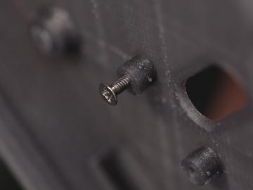
10 Download the parts and print them out accordingly - referencing the table below for material suggestions. If you don't have access to a 3D printer, use a service like 3DHubs.com ( to send them to you Dimensions Top Part 141mm x 91mm x 18mm (5.55in x 3.85in x 0.71in) Bottom Part 141mm x 91mm 16mm (5.55in x 3.85in x 0.63in) pigrrl2-top.stl Top part of case PLA/ABS pigrrl2-bot.stl Bottom of case PLA/ABS pitft-buttons.stl Buttons for PiTFT display Ninjaflex/TPE dpad.stl D-Pad for gamepad Ninjaflex/TPE action-btns.stl A,B,X and Y buttons for gamepad Ninjaflex/TPE pause-start.stl Pause and Start buttons for gamepad Ninjaflex/TPE shoulder-btns.stl Buttons for L and R shoulder buttons Ninjaflex/TPE shoulder-mount.stl Mounting plate for L and R shoulder buttons. PLA/ABS Tap Screw Holes After the parts are finished printing, you'll need to tap the standoffs with screw holes to create the threads for mounting the components. Use a #4-40 and #2-56 sized tap or use machine screws. Adafruit Industries Page 10 of 86

11 Adafruit Industries Page 11 of 86

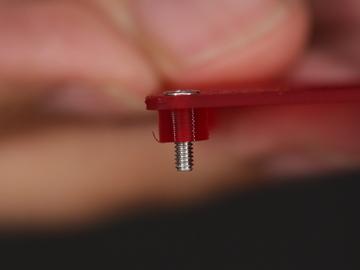
12 Be careful tapping the standoffs from the top -To prevent puncturing the surface, DO NOT tap all the way through the standoff. Be careful not to tap too fast or forcefully to avoid damaging the standoffs. Test Fit Openings Use a hobby knife to remove any excess bits from printing. Lay the components over the standoffs to see if mounting holes line up. See if the port cutouts are in the right place. If they don't, use a filing tool to open them up. Finishing Parts You can smooth the parts by applying epoxy resin like Smooth-On's XTC-3D. To finish the surface, wait for it to dry and sand it down. Apply a filler primer paint and a colored top coat of spray paint to make it extra smooth. Adafruit Industries Page 12 of 86
, then write this to an SD card (https://adafru.it/ddl) using Etcher or similar software.")
13 Software Download & Burn RetroPie Game emulation is handled by a package called RetroPie. It s a complete Linux distribution designed specifically for running classic games on Raspberry Pi. Download the current version from the RetroPie web site ( then write this to an SD card ( using Etcher or similar software. We ll then make some modifications to tune this for the PiGRRL s buttons and small display. Setup will require an HDMI monitor, USB keyboard and a network connection (either WiFi or Ethernet). This is best done before the Pi is enclosed in the PiGRRL case. If you have a spare Raspberry Pi board around, that s an ideal option you could prepare the software on that system and then move the card over to the PiGRRL 2. Setup RetroPie Insert the RetroPie card to your Pi, attach monitor and keyboard (and Ethernet, if networking that way), then power the system from a USB power source (a USB phone charger or a powered USB hub can usually work). The system will automatically reboot once (it needs this to make use of the whole SD card), then on second boot it will ask to configure the game controls The PiGRRL buttons don t work yet; this is normal. For initial setup, use the USB keyboard to select the D-pad directions (arrow keys), Start, Select, A and B keys. For anything else, just hold down the space bar or other key to skip that item. Don't worry, we'll re-do the keymap later once we've finished assembly! When finished, you ll see a graphical interface called Emulation Station where you ll select games and other options. Let s get this Raspberry Pi on the network first. If using Ethernet, it s a simple matter of plugging in. If WiFi, from the main EmulationStation screen, access the RetroPie settings using whatever key you ve assigned as the A button. You ll see WIFI in this list: Adafruit Industries Page 13 of 86
14 Here you can select your WiFi network name and enter a password. It s not beautiful, but gets the job done. Select Exit when done to return to the EmulationStation UI With networking enabled, we can now access the remaining software needed for the PiGRRL 2 experience. There are a couple ways to do this BEST: Use an ssh terminal client to log into the Raspberry Pi at retropie.local This is recommended, as you can just copy-and-paste the commands that follow. The default name and password are pi and raspberry, respectively. OR: Press F4 to exit EmulationStation for a command-line prompt (works, but you ll need to type these commands exactly). Install PiTFT (fbcp) Support This first sequence configures the system for the PiTFT display: cd curl >pitf sudo bash pitft-fbcp.sh Select the PiGRRL 2 option, which sets up various system parameters to match this project. Adafruit Industries Page 14 of 86


15 Answer NO to the reboot question Installing Keypress (retrogame) support let s take care of this second script, which enables the PiGRRL buttons: cd curl >retro sudo bash retrogame.sh Again, select the PiGRRL 2 option. When finished, now you can reboot when prompted. Adafruit Industries Page 15 of 86

16 After rebooting, the HDMI monitor may display a no signal message. This is normal. Not all monitors can handle the resolution setting we re using. Once the PiTFT is wired up, that will be the primary display. Also, after the system is assembled with the PiTFT and controls, you ll need to re-do the controller setup. This might wait til all the parts are assembled in the case. From the main EmulationStation screen, press whatever key was assigned to the Start button to access the main menu. You ll find an option here for CONFIGURE INPUT. Go through the control setup process again using the PiGRRL buttons now instead of the keyboard; assign the D-pad directions, Start and Select buttons, A, B, X and Y. For anything else, hold down a key or button to skip it. Uploading ROMs Check out the Wiki on the RetroPie Setup page for how to upload ROMs: Exiting ROMs Retropie has changed how to exit out of ROMs/Emulators. Hold down the Pause & Start buttons at the same time to exit. Remapping Controls The buttons are premapped to work with NES and SNES emulators. If you'd like to remap the controls, you'll need to modify the retrogame.cfg file in /boot. Make sure the Raspberry Pi is configured for Wifi. Open up terminal and ssh into the Pi. (Default username: pi password:raspberry) Then follow the retrogame tutorial to set it up the way you like! ( Testing Controls If you log in (via SSH or F4 shell) you can see exactly what keypresses are detected by running evtest then select 1 (or whatever retrogame is numbered): Adafruit Industries Page 16 of 86

17 Make sure each keypress works and matches the table below! Default Controls Below is a table of the controls set to the GPIO. Use this as a reference if you ever need to revert when changing something. Adafruit Industries Page 17 of 86
18 LEFT Pin 7 GPIO 4 UP Pin 36 GPIO 16 RIGHT Pin 35 GPIO 19 DOWN Pin 37 GPIO 26 SELECT Pin 29 GPIO 5 START Pin 31 GPIO 6 A Pin 8 GPIO 14 B Pin 10 GPIO 15 X Pin 38 GPIO 20 Y Pin 12 GPIO 18 L Pin 32 GPIO 12 R Pin 33 GPIO 13 Adafruit Industries Page 18 of 86

19 Gamepad PiGRRL Gamepad Design The gamepad was designed in EagleCAD and available to download and modify. It's also a shared project on Oshpark Adafruit Industries Page 19 of 86

20 PiGRRL Gamepad PCB Let's start assembly by putting the gamepad together. Gather up 10x 6mm tactile buttons and a 40pin IC box header. Adafruit Industries Page 20 of 86


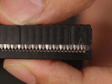
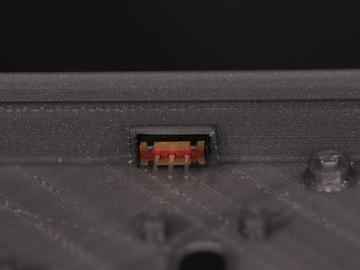
21 Install IC Box Header Insert the box header into the header labeled pin on the back of the gamepad PCB. Make sure the "notch" opening is pointing towards the "header" label. Secure it in place by adding mounting tack to the sides. Now we can secure the PCB to a Panavise to assist while soldering. Adafruit Industries Page 21 of 86


22 Solder IC Box Header Flip the gamepad PCB over so the header pins are facing up. Now heat up the soldering iron and apply solder to each of the 40 pins on the header. Ensure the solder joints are clean with no cold solder joints or blobs. They should look like Hershey's Kisses. Adafruit Industries Page 22 of 86

23 Prep 6mm Tactile Buttons To make it easier to insert the buttons to the PCB, use a pair of flat plier to straighten out the four leads of each button. Adafruit Industries Page 23 of 86


24 Install 6mm Tactile Buttons Insert each button into the through-hole spots on the gamepad PCB. Once installed, place your hand over the buttons and bend each of the leads inward so they "bite" onto the PCB - This will help hold them in place. Adafruit Industries Page 24 of 86


25 If you are using the elastomer buttons, they're still possible to use, but they wont sit perfectly flat. That's OK just make them as flat as you can! Solder Buttons to Gamepad PCB Secure the gamepad PCB to a Panavise and solder up the buttons. Make sure solder joints are clean like you did on the pins of the IC box header. Adafruit Industries Page 25 of 86

26 Soldered Gamepad PCB Here's what the soldered gamepad will look like. Clean and Shiny! Tap Gamepad PCB Mounting Holes Now is a good time to tap the mounting holes of the gamepad PCB. We need to create threads on each hole so that it's easier to mount to the case. You can use a #4-40 sized tap tool, or a #4-40 machine screw to do this, just make sure to fasten as straight as you can. Adafruit Industries Page 26 of 86
.")

27 PiTFT Display GPIO #18 - LED Backlighting Flip the 2.8" PiTFT display over and locate the pad with label #18. We need to cut this trace in order to properly use GPIO 18 (The Y Button is wired to this GPIO). By default, when GPIO 18 is triggered to ground, it will disable the LED backlighting on the display - Cutting the trace here will disable that feature. Cut Trace #18 Adafruit Industries Page 27 of 86
28 Use a hobby knife to mark in between the two pads and make sure it is deep enough to fullly break the trace. That's pretty much all we need to do to the PiTFT display! Adafruit Industries Page 28 of 86

29 PiCable PiCable Resizing In this section, we'll resize the PiCable so it's more manageable once installed inside the case. Its some what optional - you can skip it but if you find space too tight when closing the case, you may want to resize the PiCable. The stock ribbon cable is 152.4mm(6") in length, but I've found shortening it down to 108mm is just the right fit for the length we need. Adafruit Industries Page 29 of 86


30 Measure, Mark and Cut Ribbon Cable Use a pair of calipers or measuring tape to get the desired length and mark the ribbon cable - Tape, marker or otherwise. Adafruit Industries Page 30 of 86


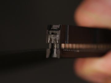
31 Cut Cable With the cable split in two, set aside the longer end and keep the short end handy - we need to remove the connector from the end of it. Removing Connector Take a close look at the bottom of the connector. You'll see two tiny holes near each side. Now take a look at the side. You'll see the connector has a clip that is held in place with a notch. The goal here is to push that clip away from the notch so we can fit the top from the connector. You can fit something small and pointy such as a needle into the holes and push the clip away from the notch while pulling the top from the connector. When the clip is free, carefully pull the top part out. You'll need to do this for both sides. Adafruit Industries Page 31 of 86


32 DO THIS SLOWLY - Be very careful not to break the clips off! Adafruit Industries Page 32 of 86


33 Peel Cable from Connector With the top removed from the connector, carefully peel the ribbon cable from the connector. You should be left with the top part and the female connector. You can discard the ribbon cable. Slowly peel the ribbon cable off - If any metal bits come out, carefully push them back into the connector. Install Connector to Shortened Ribbon Cable Grab the longer piece of the ribbon cable from earlier and lay the cut end over the top piece - The ribbon cable should nicely fit into the grooves of the top piece. Now grab the female connector and insert the top piece into back onto the connector. Make sure the arrow/triangle marking lines up with the side of the ribbon cable with the single white colored wire. Press the two pieces together and make sure the clips nicely fit into the sides of the connector. Adafruit Industries Page 33 of 86

34 Adafruit Industries Page 34 of 86


35 Mash Top Piece to Connector Unless you're incredibly strong, you won't be able to press the top piece back onto the connector because it's hard to puncture the wire with the pointy teeth. The easiest way to do this is to use a rubber mallet to smash the pieces together. I recommend doing this on a hard surface (like on the floor) while holding the connector in place. Tap the top piece in sessions as straight as you can and be careful not to mash your fingers in the process. If all goes well, the teeth from the connector will puncture the ribbon cable and close the two pieces back together. Shortened Pi Ribbon Cable Adafruit Industries Page 35 of 86
36 And there you have it! A shortened Raspberry Pi Ribbon Cable. Bit of a hack, I know - But it really does make closing the case much easier in when we're all done. Adafruit Industries Page 36 of 86


37 Amp & Speaker Prep PAM8302 Amp Secure the amp to a pair of helping third hands. Use the tip of the soldering iron to heat up solder and apply to the VIN, GND, A+, A, + and pins. This will make it easier to solder wires to the pins. Adafruit Industries Page 37 of 86

38 Measure Wires for Amp and Speaker We'll need two pieces of 30AWG wires to connect the speaker to the amp. We recommend using silicone-coated stranded wire. Measure about 9cm in length for each wire. You don't have to use different colored wires, but we recommend it to help tell them apart. Adafruit Industries Page 38 of 86


39 Strip and Tin Wires Use a pair of wire strippers to remove about 4mm of insulation from the tips of each wire. To keep the tips of wires from fraying, use the tip of the soldering iron to apply solder. You can bundle the tips of wires together and use a pair of helping third hands to tin the tips at the same time. Adafruit Industries Page 39 of 86

 and negative (left pad).")
40 Connect Wires to Speaker Remove the wires connected to the speaker, they're too short. We'll need to connect the new pieces of wire we just prepped onto the solder pads of the speaker. Secure the speaker to the helping third hands - Since there's a magnet on it, we can stick it to one of the grabber arms. Reference the photo to see which is positive (right pad) and negative (left pad). Next, slip on a piece of heat shrink tubing to group the two wires. Adafruit Industries Page 40 of 86


41 Connect Wires to Amp Secure the amp back onto the helping third hands. Solder the positive wire from the speaker to the positive output pin on the amp, then, solder the negative wire to the negative output pin. Now we can proceed to work on the power circuit. Adafruit Industries Page 41 of 86
 out, Negative( ) out, EN, GND, G and 5V. Adafruit Industries https://learn.")
42 Power Circuit Prep PowerBoost 1000C Secure the PowerBoost to the pair of helping third hands. Apply solder to the following pins: Positive(+) out, Negative( ) out, EN, GND, G and 5V. Adafruit Industries Page 42 of 86


43 Measure Wires for PowerBoost and Amp We'll need about 3cm in length of 30AWG wire to connect the Amp to the PowerBoost 1000C. Use wire strippers to remove about 4mm of insulation from each tip and apply solder to tin them. Now secure the amp to the helping third hands and solder the wires to the Vin and Gnd pins. Adafruit Industries Page 43 of 86


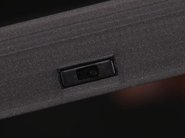
44 Connect Amp to PowerBoost 1000C Slip on a piece of heat shrink tubing to the wires connected to the Vin and Gnd pins. Next, secure the PowerBoost 1000C to the helping third hands. Solder the VIN wire from the amp to the 5V pin on the PowerBoost. Then, solder the Gnd wire from the amp to the G pin on the PowerBoost 1000C. Connected Amp, Speaker and PowerBoost 1000C Now our amplifier and speaker are wired up the PowerBoost 1000C. Test fit Power Switch Next up we need to connect our slide switch to the PowerBoost 1000C. First, we should do a test fit and see if our switch can fit into the case. Insert the switch into the switch cutout of the bottom case. Press it all the way through. If it's too tight, you can use a filing tool to open it up. Adafruit Industries Page 44 of 86

45 Adafruit Industries Page 45 of 86


46 Prep Slide Switch Remove one of the legs from the slide switch. Secure the switch to the helping third hands and apply solder to the two remaining legs. Now we'll need two new 30AWG wires that measure abot 7cm in length. Strip and tin the tips of each wire. Adafruit Industries Page 46 of 86


.")
47 Connect Wires to Switch Solder the two wires to the two leads of the slide switch. Add pieces of heat shrink tubing to each terminal to insulate them. Connect Switch to PowerBoost 1000C Now we need to solder the two wires to the EN and GND pins of the PowerBoost. The polarity doesn't matter that much here. The switch can be installed in your prefered position later (ie. Up position is ON, Down position if OFF, it's up too you!). Adafruit Industries Page 47 of 86

48 Wired Power Circuit Now we have our amp, speaker, PowerBoost and slide switch all wired up and connected. Now's a good time to take a break or continue! Adafruit Industries Page 48 of 86


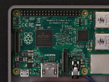
49 Pi Audio Prep Wires for Rasp Pi Audio To connect the amp to the Raspberry Pi 2, we'll need two wires. Cut two pieces of 30AWG wires to about 10cm in length. Strip and tin the tips of each wire. Prep Raspberry Pi Audio Pins On the bottom of the Raspberry Pi 2 PCB, locate the audio jack and inspect the three pin connected to the component. Adafruit Industries Page 49 of 86
. Place the tip of the soldering iron over the pin and apply a small amount of solder.")
50 Take note of the two circles highlighting the pins. The left pin (blue) will connect to the negative pin on the amp, while the right pin (red) connects to the positive pin. The middle pin does not need to be tinned (disregard the tinning in the photo). Place the tip of the soldering iron over the pin and apply a small amount of solder. This will make connecting wires to the audio amp much easier. Connect Wires to Raspberry Pi Solder the new wires to the pins on the bottom of the Raspberry Pi. The negative(blue) wire connects to the left pin, while the positive(ed) wire connects to the right pin. Adafruit Industries Page 50 of 86
.")
51 Connect Wires to Amp Solder the negative (blue) wire to the A pin on the amp, and the positive (red) wire to the A+ pin on the amp. Audio Connection Confusion? You may notice the audio connections in the photo above are reserved. This photo is intended for the Pi 1 Model B+ (not the 2 or 3). Be sure to follow the first set of photos if you're using the Pi 2 or 3. If your using the Pi 1 Model B+, then reference the photo above. Adafruit Industries Page 51 of 86


52 Shoulder Buttons Prep 12mm Tactile Buttons Next up we need to prepare two 12mm buttons for our shoulder L and R buttons. Start by clipping two of the four legs from each button. Use a pair of flat pliers to flatten out the legs so they point out like in the photo. Secure the button to a pair of helping third hands and apply solder to each leg to tin them. Prep Wires for Shoulder Buttons Adafruit Industries Page 52 of 86


53 We'll need two sets of wires (four total) to measure about 14cm in length. Strip and tin the tips from each wire and thread them through one big piece of heat shrink tubing. This will keep the wires together in a neat bundle. Connect Wires to Buttons Solder wires to the legs of each button - Like before, use a pair of helping third hands to assist you. Polarity doesn't matter too much on these buttons, but you can reference the photo. Shoulder Buttons Adafruit Industries Page 53 of 86
54 OK, now we have our shoulder buttons prepped and ready to wire into our gamepad PCB. The next page will go through the final connections for our build. Adafruit Industries Page 54 of 86
 that's about 14cm in length. Like before, strip and tin the ends of each wire.")
55 Final Connections Prep Wires for Gamepad PCB Now we need to connect our gamepad PCB to the PowerBoost 1000C. We'll need two 26AWG (which is thicker than the 30AWG we've been using so far) that's about 14cm in length. Like before, strip and tin the ends of each wire. Then, let's slip on a long piece of heat shrink tubing to keep the two wires together. Adafruit Industries Page 55 of 86

.")
56 Prep Power Pins on Gamepad PCB Locate the power label on the gamepad PCB and take note of the 5V and GND pins. Flip the gamepad PCB over and secure it to a Panavise to hold it in place. Apply solder to the two pins and solder in our two 26AWG wires. Use the photo to reference which wires goes were (red right, white left). Adafruit Industries Page 56 of 86


57 Connect Shoulder Buttons to Gamepad PCB Locate the bumper labeled pins on the opposite side of the gamepad PCB. Referencing the photo, from the bottom up, the order of pins are: L button, R button, Ground, Ground. Once you're familiar with the pin order, solder in the wires from the 12mm tactile buttons. Adafruit Industries Page 57 of 86


58 Connect Gamepad PCB to PowerBoost 1000C Now we can solder in the two wires connected to the power pins of the gamepad PCB to the power output pin on the PowerBoost. The 5V wire from the gamepad connects to the positive pin on the PowerBoost, and the Ground wire from the gamepad connects to the negative pin on the PowerBoost. Final Wired Components OK, now all of our wires are connected, yay! Our components are connected and we're ready to mount them to the case. In the next page, we'll finish up our build! Adafruit Industries Page 58 of 86
59 Test Components Its good practice to test all of our components before we start mounting things to the enclosure. Just as a sanity check, this ensures our components and wiring is all good and working. Go ahead and insert your microsd card into the Raspberry Pi - make sure the software is already installed and loaded. Once thats sorted, plug in the JST connector from our battery into the PowerBoost 1000C. Next, plug the Pi ribbon cable into the PiTFT GPIO breakout and connect the other end to the PiGRRL Gamepad. Then, lay the PiTFT over the Raspberry Pi and press it down to connect together the GPIOs until they re fully seated. Now you can flip the slide switch to power on the circuit. The PiTFT should display the boot up scripts and automatically launch RetroPi Emulationstation. Test out the DPad and buttons to see if everything works as expected. You should hear audio once a ROM is loaded. If you don t have any loaded, reference the software page for uploading ROMs (You should be able to launch Quake from the Ports section). If the audio isn t working, or the buttons aren t triggering, you ll want to double check your wiring. If you are not sure how to use a multi-meter to check for any shorts and continuity, you may want to post up any specific issues in the Adafruit Forums, where our dedicated engineering support team can help you trouble shoot. If everything works during your test, you should be safe to power down the Raspberry Pi and move onto the next page. Adafruit Industries Page 59 of 86


60 Mount Components Install 2.8" PiTFT The first component we need mount to the case is the display screen. Before we do that, we'll need to insert the PiTFT rubber buttons into the case. Place them over the cutouts from the inside of the top case and press them into place. Now that the PiTFT button actuators are in place, lay the PiTFT screen over the case. Line up the mounting holes with the standoffs. Then, insert #4-40 3/8 sized machine screws into each mounting hole and fasten them into place. Be careful not to apply excess force, and fasten slowly. Adafruit Industries Page 60 of 86


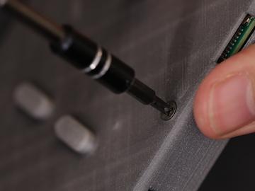
61 DO NOT insert screws all the way through standoffs! Reference the photo to see required depth. Install Gamepad PCB Next up, let's fasten #4-40 3/8 sized machine screws into the mounting holes on the corners of the gamepad PCB. Insert them from the top of the PCB so that they're just barely protruding from the back side. This makes it easier to mount it to the standoffs in the case. Now, insert the rubber D-Pad, Action Buttons and Pause/Start actuators into the cutouts of the top case part. Place the gamepad PCB over the standoffs and line them up with screws. Slowly (and carefully) fasten the screws into the standoffs. However, DO NOT fasten them all the way through! Only fasten them down until they're deep enough to be lower than the height of the case. Please reference the photo - if screws are inserted too far, they could protrude through the surface of the case. Adafruit Industries Page 61 of 86


62 Adafruit Industries Page 62 of 86


63 Connect Pi Cable Next, we can install the Pi Cable to conenct the Gamepad PCB to the PiTFT display. The orientation of the Pi cable is important, so reference the photo and follow the markings. Adafruit Industries Page 63 of 86

64 Connected PiTFT and Gamepad Now our PiTFT display and Gamepad PCB are mounted to the case. Press the buttons on the PiTFT and Gamepad to test them and see they feel good. If the buttons get stuck, the gamepad isn't flush with the standoffs. Install Speaker Let's go ahead and pop the speaker into the case. Lay the speaker over the cavity with the grill and press it down to snap it into place. The wire should be oriented in a position so it's not in the way of the corner standoff. Adafruit Industries Page 64 of 86


65 Shoulder Button Mount Next up we need to mount our two shoulder buttons to the shoulder mounting piece. To do that, we can use adhesives such as E600 or hotglue - But I've found using mounting tack works just fine (plus, it makes it adjustable if we don't position it correctly the first time around). Add the tack to the back of the 12mm button and position them over the two recessed square spots on the mounting part. Press them down to stick them into place. Adafruit Industries Page 65 of 86


66 Shoulder Button (cont.) Fasten four #2-56 3/8 into the standoffs of the shoulder mount. Screw them in until the barely protrude the standoff - this is going to make it easier to mount it to the case. Next, insert the rubber shoulder button actuator into the cutout of the bottom case part. Adafruit Industries Page 66 of 86


67 Install Shoulder Button Mount Place the shoulder mount over the standoffs on the bottom case. Make sure the screws line up with the standoffs - they're position / orientation specific. Once they're lined up, carefully fasten the screws down. Here, you can fasten them all the way. Adafruit Industries Page 67 of 86
. Install Raspberry Pi 2 Next up, lets mount the Pi to the bottom case.")

68 Install Switch Now if a good time to insert the slide switch into the bottom case. Take note of the OFF position of the slide and install it to your liking (I prefer down is OFF, up is ON). Install Raspberry Pi 2 Next up, lets mount the Pi to the bottom case. First, let's fasten #4-40 3/8 sized machine screws to the two mount holes on the back of the bottom case part. Like the previous mounting standoffs, fasten the screws so they're just barely protuding through the top of the standoffs. Then, lay the Pi over the standoffs and line up the screws with the mounting holes. Once in place, fasten the screws all the way until they're flush with the surface of the case. Adafruit Industries Page 68 of 86

69 Adafruit Industries Page 69 of 86


70 Mount PowerBoost 1000C We'll need two #4-40 3/8 machine screws to install the PowerBoost to the case. Fasten the screws to the two mounting holes of the PowerBoost - This will create threads. Once they're made, lay the PowerBoost over the standoffs (close to the center bottom). Hold the PCB in place while fastening the screws to the standoffs. Don't fasten these screws all the way through, just deep enough they go past the heigh of the case - similar to the other components. Adafruit Industries Page 70 of 86


71 Mount Amp Insert and fasten a single #4-40 3/8 machine screw into the mounting hole of the amp PCB (should be the hole closest to the Adafruit logo) - This will help create the screw threads. Then, place the PCB over the standoffs and hole it down to fasten the screw into the standoff. Adafruit Industries Page 71 of 86

72 Test PowerBoost Circuit Grab the lipo battery and plug in the JST connector to the JST port on the PowerBoost 1000C. Flip the slide switch on, and see if the circuit works! The blue LED indicates the battery is charged and the circuit is powered on. If the LED doesn't light up, you either have a defective PowerBoost, or a short. You'll have to double check your wiring for short using a a multi-meter. If you have any issues or questions, please post it on support forums at ( Adafruit Industries Page 72 of 86


73 Install Lipo Battery Now we can install the 2000mAh lipo battery. A good spot for it is right behind the PiTFT display. To keep it in place, we can use a piece of gaffers tape. Try to keep it up closely against PiCable. Position it like in the photo, closer to the right side to avoid intersecting with some of the components from the Pi. Almost Done! In the next page, we'll close up the case and finish the build! Adafruit Industries Page 73 of 86


74 Close It Up! Join Parts Now its time to close it all up. Before that, make sure all of the wires are inside the case. Wires should be neaty tucked and away of kinking from any of the components. Bring the top and bottom parts together and press the bottom part together. They should snap together. Then, inspect the edges and see if everything is in place - no wires hanging out. If it looks good, start pressing the top area close together - Slowly. If you can't squeeze the top together, the battery could be in the way - be sure to check that and ensure its not in the way of any of the components. Adafruit Industries Page 74 of 86


75 Screw Bottom Portion There's two spots on the bottom that feature counter bore standoffs - insert a #2-56 3/8 machine screw and fasten them all the way. This will keep the bottom from coming part. Adafruit Industries Page 75 of 86

76 Insert microsd Card Lastly, insert the microsd card if you haven't already. You should have already burnt the PiGRRL image to the SD card. If not, go ahead and do that now! Completed Build! Hazzah! The PiGRRL 2 game console is finally finished and ready to play! Turn it on and RetroPie / Emulationstation should automatically boot. The buttons are premapped to the expected controls. Reference the Software page for uploading ROMs and remapping controls. Share Your Creation With Us! If you built PiGRRL 2, we'd love to see it and share it with the community! Post a make on the thingiverse project page, share it on Instagram or twitter with hashtag #PiGRRL2. Adafruit Industries Page 76 of 86


77 Trouble Shooting Buttons don't work, things are very weird Make sure you didn't plug the Pi cable in backwards, you can use a multimeter to check that these voltages are correct when the Pi is powered: Audio Issues Are you hearing a strange sound when powering up the Pi? The battery might be in a bad spot where it's causing interference noise with the audio jack. If you remove the mounting screws from the Pi on the back of the bottom case, you can separate the two parts while it's still powered. Adafruit Industries Page 77 of 86

78 Once they're separated, reposition the battery and listen carefully to the noise. Position the battery in a spot where the noise is less prominent and mount it in place with tape or mounting tack. Another option you can try is to adjust the pot on the sound amp. Lowering the gain may fix the sound interference when repositioning the battery doesn't work. The best location for the battery I've found is directly tucked inbetween the Raspberry Pi and the PiTFT display. No Audio Retropie has sound options built into the software. It may be muted or set to really low. To adjust it, press the "Start" button to bring up the Menu. Then, use the D-Pad to highlight Sound Settings. Use the A button to select and D- Pad to increase volume. Press the B button to exit. Pressing Button Turns Off Screen If the PiTFT display turns black when you press one of the gamepad buttons, the trace that controls the backlighting might need to be cut deeper. The label #18 on the back of the PiTFT is active by default - triggering it turns the display off. Make sure this trace is cut to deactivate this feature. Button on pin #18 doesn't work You didn't cut the trace on the #18 pad, make sure to do that PiTFT Shows Only White Screen If the PiTFT display only display a white screen, chances are the img wasn't properly burnt to the SDcard. Be sure to follow the steps Easy SD Card Setup ( guide to correctly burn the image. Custom Mute Function Adafruit Industries Page 78 of 86
79 If you're interested in making one of the PiTFT buttons mute the audio, Martin O'Hanlon made a function. Better Sound quality A suggestion from the forums ( 1)Wrap the battery in copper tape and then electrical tape. Then you solder a wire from the ground of the audio circuit to the copper. It helps to solder to a random piece and then stick it to the battery so you're not soldering on the battery itself as it's dangerous. 2)Buy tiny ferrite beads and put them around the speaker wires. Ferrite beads provide EMI shielding and putting them around the speaker wires worked like a charm. Issues, Problems, Need Help? If you encounter any technical problems with the Raspberry Pi software, components or otherwise, please post up your issue, including photos of your wiring on the Adafruit Forums. Our support team will be able to assist you there. Adafruit Industries Page 79 of 86
80 Extras Safely Shutdown via Tactile Switch Its a good idea to safely turn off your Pi with a good sudo shutdown -h now but that often means pulling out a keyboard or connecting to the console. With our kernel we added a cool module that will let you turn any GPIO into a power button. Since there's a couple of tactile switches right there on the front, lets turn one into a power button. Press once to properly turn off the pi, press again to start it up. Isn't that nice? Adafruit Industries Page 80 of 86
81 Troubleshooting RetroPie and retrogame This page documents the most common pitfalls encountered when making retro gaming projects, offering some solutions and where to turn for further help. There are some things we can fix and some we can t we re not involved in RetroPie s development, for example but we ll try to point you in the right direction. Most of the following troubleshooting steps will require a USB keyboard attached. Some require a network connection. retrogame Related Troubleshooting retrogame is our software that converts GPIO button actions into keyboard events. These are the problems we re best equipped to fix. Some common things to check for any retrogame installation: Confirm button/joystick wires go to the correct pins and to ground. A multimeter with a continuity beep function is helpful for testing. The retrogame configuration file (/boot/retrogame.cfg) uses Broadcom pin numbers these are not sequential along the GPIO header pins. This site has a nice reference chart ( (use the BCM numbers). Earlier versions of retrogame didn t use a configuration file you had to edit and compile the source code. That s just horrible. If you re running an early version like that, this would be a good time to upgrade. See the Installing Retrogame ( page. Some of my buttons/controls aren t working! Check connections and configuration file pin numbers as explained above. (If some controls are responding, that s an encouraging start it at least means the code is running.) The key codes generated by retrogame might not be assigned to EmulationStation s keyboard inputs; one or the other will need to be changed. Either edit /boot/retrogame.cfg, or, from the EmulationStation main screen, press Start to access the main menu, then select Configure Input and proceed through each of the controls. NONE of my buttons/controls are working! Confirm that retrogame is actually running either exit to the command line (F4) or log in using ssh, then use ps -ef grep retrogame to check. If you used our installer script or one of our ready-made SD card images, it should be started automatically on boot (added to /etc/rc.local). Confirm that the file /etc/udev/rules.d/10-retrogame.rules exists. Our installer script creates this file, but if you installed retrogame manually or from source, it may have been overlooked. My controls only work if there s also a USB keyboard plugged in! Confirm that the file /etc/udev/rules.d/10-retrogame.rules exists. Our installer script creates this file, but if you installed retrogame manually or from source, it may have been overlooked. Retrogame doesn t work with my optical buttons! Unfortunately, yes. retrogame only works with passive switches between a GPIO pin and ground (logic low=pressed). It won t work with switches that have the opposite logic level (high=pressed). I ran Adafruit s retrogame installer script and rebooted, and now the keyboard and network are unresponsive! This can happen if you re running an early Raspberry Pi (Model A or B) with the 26-pin GPIO header and select the Adafruit Industries Page 81 of 86
82 Six buttons + joystick option in the retrogame installer. That particular configuration is set up for our Arcade Pack and newer (40 pin) Raspberry Pi boards. Some of the pin numbers referenced don t exist on the older 26-pin header and lead to trouble. If this happens to you, not to worry. Power off the Pi and insert the SD card in a reader on a PC or Mac. Look for a file called retrogame.cfg edit this file and change the pin numbers to match your specific controller wiring. RetroPie Related Troubleshooting RetroPie provides the actual emulation software and a nice user interface. As this is third-party code, the depth of problems we can troubleshoot is more limited, but here are some of the common issues we ve seen and how to resolve them My controls work in the EmulationStation UI, but not in one or more specific emulators! This can happen with certain emulators (usually older or more esoteric ones) that don t use the libretro library. Among other things, libretro allows the global controller configuration to be used everywhere. There are a couple of workarounds that might help, but no guarantees You can rummage around in /opt/retropie/configs and look for a configuration file specific to the problem emulator, then edit its keyboard layout to match your controls. The format of this file, if one even exists, is likely specific to that one emulator, so you ll need to do some research (Google search, etc.), it s not something we can help out with. You can try hunting for an alternate emulator based on libretro, if there s one available (see Installing RetroPie Packages below). The ROM files I have worked in a different emulator before, but aren t working in RetroPie! This can happen if the ROM file format changes between versions of an emulator, or if two emulators for the same system use different formats. Do some research (Google search, etc.) to see if this is the case. It s possible there may be utilities to convert among different ROM formats. Try installing an alternate emulator, if there s one available (see Installing RetroPie Packages below). A few emulators may require a BIOS file in order to function, but it s not included with the software for legal reasons. This is something you ll have to research and track down. Installing RetroPie Packages To add support for a system not present in RetroPie by default, or to add an alternate emulator program for an existing system, select RetroPie Setup from the RetroPie menu. This brings up a text-menu-based interface and will require a USB keyboard to navigate. Select Manage packages and then one of the core, main, optional or experimental selections you ll probably want to navigate through each of them to see what s available, keeping in mind that each successive category might be a little rougher around the edges. Your best bet are packages whose names begin with Adafruit Industries Page 82 of 86

83 lr-. This means they re built using libretro and the control inputs should already work with what you have! Other packages may require their own manual controller setup, which can be a real nuisance. When asked, select Install from binary. The source option takes much longer and won t provide any benefit for the average user only attempt that if you know you need absolutely bleeding-edge code. It s totally valid to install multiple emulator packages that handle the same type of system. Each might have different performance or compatibility benefits, so it s worth testing your options. See Accessing Alternate Emulators below. Adafruit Industries Page 83 of 86


84 Accessing Alternate Emulators Adafruit Industries Page 84 of 86


85 When you launch a game, you ll briefly see this nondescript launching message. You have a couple of seconds to hit a button or key The first option in this configuration menu lets you select a different emulator package for a given system type or even on an individual ROM-by-ROM basis, if different games benefit from different emulation software. Test it out with. If you don t like the results, next time you launch that game you can access the configuration menu again and restore the original selection. More RetroPie Help For issues not covered above, the best sources for RetroPie-specific help are the official documentation and forum on the RetroPie web site: RetroPie Documentation ( RetroPie Forum ( Adafruit Industries Page 85 of 86
7 Portable Multitouch Raspberry Pi Tablet
 7 Portable Multitouch Raspberry Pi Tablet Created by Ruiz Brothers Last updated on 2017-02-27 04:13:53 PM UTC Guide Contents Guide Contents Overview Portable Raspberry Pi Tablet 7" Multitouch Display Parts
Feather Weather Lamp. Created by Ruiz Brothers. Last updated on :54:26 PM UTC
 Feather Weather Lamp Created by Ruiz Brothers Last updated on 2018-08-22 03:54:26 PM UTC Guide Contents Guide Contents Overview Weather Reactive Pixels Prerequisite Guides Parts Tools & Supplies Circuit
Portable Apple Watch Charger
 Portable Apple Watch Charger Created by Ruiz Brothers Last updated on 2017-10-22 09:58:04 PM UTC Guide Contents Guide Contents Overview Smart Charging Prerequisite Guides Parts, Tool & Supplies Circuit
Pocket PiGRRL. Created by Ruiz Brothers. Last updated on :47:31 PM UTC
 Pocket PiGRRL Created by Ruiz Brothers Last updated on 2018-08-22 03:47:31 PM UTC Guide Contents Guide Contents Overview Raspberry Pi This Guide Prerequisite Guides Parts Tools Supplies Circuit Diagram
7" Portable HDMI Monitor
 7" Portable HDMI Monitor Created by Ruiz Brothers Last updated on 2017-05-29 05:47:14 PM UTC Guide Contents Guide Contents Overview DIY Monitor Connect to a Raspberry pi Use as a second monitor Camera
FPV Mini Display. Created by Ruiz Brothers. Last updated on :00:18 PM UTC
 FPV Mini Display Created by Ruiz Brothers Last updated on 2017-07-19 01:00:18 PM UTC Guide Contents Guide Contents Overview Mini FPV monitor Adafruit Parts Tools and Supplies Circuit Diagram Electronics
Solar Boost Bag. Created by Becky Stern. Last updated on :44:55 PM UTC
 Solar Boost Bag Created by Becky Stern Last updated on 2018-08-22 03:44:55 PM UTC Guide Contents Guide Contents Overview 3D Design Files Customize Design Assemble Circuit Prepare Solar Panel Enclosure
Mini Mac Pi. Created by Ruiz Brothers. Last updated on :43:27 PM UTC
 Mini Mac Pi Created by Ruiz Brothers Last updated on 2018-08-22 03:43:27 PM UTC Guide Contents Guide Contents Overview Build Your Own Mac Pi How it Works Project Advisory Challenges and Expectations Prerequisite
Trinket NeoPixel LED Longboard
 Trinket NeoPixel LED Longboard Created by Ruiz Brothers Last updated on 2017-10-02 06:00:32 PM UTC Guide Contents Guide Contents Overview Parts Tools & Supplies Prerequisite Guides 3D Printing PLA Material
DIY Bluetooth Gamepad
 DIY Bluetooth Gamepad Created by Ruiz Brothers Last updated on 2016-09-03 02:23:21 AM UTC Guide Contents Guide Contents Overview Prerequisite Guides Expectations Parts Tools & Supplies Circuit Diagram
3D Printed Case for Adafruit Feather
 3D Printed Case for Adafruit Feather Created by Ruiz Brothers Last updated on 2018-08-22 03:59:38 PM UTC Guide Contents Guide Contents Overview Adafruit Feather Box New Update! Check out the TFT Feather
LED Eyes. Created by Ruiz Brothers. Last updated on :50:55 AM UTC
 LED Eyes Created by Ruiz Brothers Last updated on 2018-01-13 05:50:55 AM UTC Guide Contents Guide Contents Overview Parts, Tools and Supplies Enameled Copper Magnet Wire 11 meters / 0.1mm diameter Adafruit
Raspberry Pi Pipboy 3000
 Raspberry Pi Pipboy 3000 Created by Ruiz Brothers Last updated on 2017-08-09 01:44:21 AM UTC Guide Contents Guide Contents Overview Functional Cosplay Props Electronic Parts & Components Tools & Supplies
Simple LED Unicorn Horn
 Simple LED Unicorn Horn Created by Ruiz Brothers Last updated on 2018-08-22 03:56:14 PM UTC Guide Contents Guide Contents Overview 3D Printed Unicorn Horn Want More Magic/Colors? Great For Beginners Parts
Bluetooth Controlled NeoPixel Headphones
 Bluetooth Controlled NeoPixel Headphones Created by Ruiz Brothers Last updated on 2017-03-09 07:38:05 PM UTC Guide Contents Guide Contents Overview Smart LED HeadPhones Prerequisite Guides Parts Tools
Trellis 3D Printed Enclosure
 Trellis 3D Printed Enclosure Created by Ruiz Brothers Last updated on 2018-08-22 03:39:07 PM UTC Guide Contents Guide Contents Overview Parts Tools & Supplies Modeling 123D Design Customize Measuring Parts
3D Printed 20w Amplifier Box
 3D Printed 20w Amplifier Box Created by Ruiz Brothers Last updated on 2018-02-26 06:48:02 PM UTC Guide Contents Guide Contents Overview Prerequisite Guide Tools & Supplies Parts 3D Printing Print in your
3D Printed Google AIY Voice Kit
 3D Printed Google AIY Voice Kit Created by Ruiz Brothers Last updated on 2018-01-09 12:47:26 AM UTC Guide Contents Guide Contents Overview 3D Print a DIY AI enclosure for the Raspberry PI! Parts, Tools
NeoPixel Bike Light. Created by Ruiz Brothers. Last updated on :43:46 PM UTC
 NeoPixel Bike Light Created by Ruiz Brothers Last updated on 2018-11-15 07:43:46 PM UTC Guide Contents Guide Contents Overview 3D Printed Headlight Adafruit's Feather Platform Circuit Python Powered Parts
Neon LED Signs. Created by John Park. Last updated on :11:09 PM UTC
 Neon LED Signs Created by John Park Last updated on 2018-08-22 04:11:09 PM UTC Guide Contents Guide Contents Overview Parts Materials Tools Build the Sign Driver Preparation Solder the Circuit Solder the
PyPortal View Master Created by Ruiz Brothers. Last updated on :51:28 AM UTC
 PyPortal View Master Created by Ruiz Brothers Last updated on 2019-03-13 11:51:28 AM UTC Overview In this project we re building a view master inspired device using Adafruit s PyPortal. The eyepiece makes
Boomy The Boombox. Created by Ruiz Brothers. Last updated on :52:13 PM UTC
 Boomy The Boombox Created by Ruiz Brothers Last updated on 2017-09-05 08:52:13 PM UTC Guide Contents Guide Contents Overview Boomy The Boombox AdaBox 004 Parts 3D Printing 3D Printed Parts Enclosure Design
FLORA TV-B-Gone. Created by Becky Stern. Last updated on :32:57 PM UTC
 FLORA TV-B-Gone Created by Becky Stern Last updated on 2018-08-22 03:32:57 PM UTC Guide Contents Guide Contents Overview Parts Tutorials Transistors Resistors LEDs Pushbutton Program it Power Fabric pinwheel
3D Printed 20w Amplifier Box
 3D Printed 20w Amplifier Box Created by Noe & Pedro Ruiz Last updated on 2014-04-22 03:01:38 PM EDT Guide Contents Guide Contents Overview Prerequisite Guide Tools & Supplies Parts 3D Printing Print in
Adafruit Pi Cobbler Kit
 Adafruit Pi Cobbler Kit Created by lady ada Last updated on 2018-08-22 03:30:27 PM UTC Guide Contents Guide Contents Overview Solder it! Buy a Pi Cobbler Kit! Downloads 2 3 5 15 16 Adafruit Industries
Adafruit VL53L0X Time of Flight Micro-LIDAR Distance Sensor Breakout
 Adafruit VL53L0X Time of Flight Micro-LIDAR Distance Sensor Breakout Created by lady ada Last updated on 2017-12-28 11:56:14 PM UTC Guide Contents Guide Contents Overview Sensing Capablities Pinouts Power
3D Printed Camera LED Ring
 3D Printed Camera LED Ring Created by Ruiz Brothers Last updated on 2018-08-22 03:39:34 PM UTC Guide Contents Guide Contents Overview DIY LED Ring Light Prerequisite Guide: Parts List: Tools & Supplies
i2c/spi LCD Backpack Created by lady ada Last updated on :11:04 PM UTC
 i2c/spi LCD Backpack Created by lady ada Last updated on 2017-08-16 05:11:04 PM UTC Guide Contents Guide Contents Overview Which LCD to Use? Wait - the backpack has 16 holes, but my LCD only has 14 pins!
Circuit Playground Express Head-Tilt Ears
 Circuit Playground Express Head-Tilt Ears Created by Dave Astels Last updated on 2018-10-09 04:07:03 PM UTC Guide Contents Guide Contents Overview Parts Circuit Playground Express Micro servo Lithium Ion
Cup o' Sound. Created by Becky Stern. Last updated on :30:06 PM EST
 Cup o' Sound Created by Becky Stern Last updated on 2015-02-18 01:30:06 PM EST Guide Contents Guide Contents Overview Circuit Diagram Load Sound and Prepare Components Solder Circuit and Assemble Use it!
Adafruit Prototyping Pi Plate. Created by Ladyada
 Adafruit Prototyping Pi Plate Created by Ladyada Guide Contents Guide Contents Overview Solder it! User Manual Buy Adafruit Prototyping Pi Plate 2 3 4 14 17 Adafruit Industries http://learn.adafruit.com/adafruit-prototyping-pi-plate
Circuit Playground Combadge
 Circuit Playground Combadge Created by Ruiz Brothers Last updated on 2017-10-22 10:42:02 PM UTC Guide Contents Guide Contents Overview What's a Combadge? DIY Combadge How Does It Work? Make It How You
Raspberry Pi Selfie Bot
 Raspberry Pi Selfie Bot Created by Sophy Wong Last updated on 2018-08-22 04:03:16 PM UTC Guide Contents Guide Contents Overview Parts & Supplies The Circuit Power Circuit Other Connections Laser Cutting
Audio Prank Gift Box. Created by Becky Stern. Last updated on :46:15 PM UTC
 Audio Prank Gift Box Created by Becky Stern Last updated on 2018-08-22 03:46:15 PM UTC Guide Contents Guide Contents Overview Circuit Diagram Prepare Components Build Circuit Wrap and Give 2 3 5 6 12 14
Adafruit DRV2605 Haptic Controller Breakout
 Adafruit DRV2605 Haptic Controller Breakout Created by lady ada Last updated on 2018-08-20 03:28:51 PM UTC Guide Contents Guide Contents Overview Pinouts Power Pins I2C Pins Other! Assembly Prepare the
Ping Pong Ball Launcher
 Ping Pong Ball Launcher Created by Dano Wall Last updated on 2019-01-25 03:19:13 AM UTC Guide Contents Guide Contents Overview Electronic Parts Circuit Playground Express USB cable - USB A to Micro-B Alkaline
This isn t a complete guide, but it should show you enough to figure out how I did this and that.
 I wanted to fit a Raspberry Pi running Retropie into a Gameboy Advance SP case. I didn t want to cut any new holes and it had to close up completely; no wires sticking out, no extra buttons in places they
Circuit Playground Yoyo
 Circuit Playground Yoyo Created by Ruiz Brothers Last updated on 2018-01-13 05:56:02 AM UTC Guide Contents Guide Contents Overview 3D Printed NeoPixel Yoyo History of the Yo-Yo Expectations Parts Tools
No-Sew LED Wristband. Created by Kathy Ceceri. Last updated on :23:40 PM UTC
 No-Sew LED Wristband Created by Kathy Ceceri Last updated on 2018-11-13 09:23:40 PM UTC Guide Contents Guide Contents Overview Playing with LED Options Suggested Parts List -- Electronics Suggested Materials
Adafruit Capacitive Touch Sensor Breakouts
 Adafruit Capacitive Touch Sensor Breakouts Created by Bill Earl Last updated on 2018-08-22 03:36:13 PM UTC Guide Contents Guide Contents Overview Momentary Toggle 5-Pad Momentary Assembly and Wiring Installing
Adafruit AMG8833 8x8 Thermal Camera Sensor
 Adafruit AMG8833 8x8 Thermal Camera Sensor Created by Justin Cooper Last updated on 2017-11-27 10:00:27 PM UTC Guide Contents Guide Contents Overview Pinouts Power Pins: Logic pins: Assembly Prepare the
Phone-Activated Talking Dog Collar
 Phone-Activated Talking Dog Collar Created by Phillip Burgess Last updated on 2017-01-24 08:28:00 PM UTC Guide Contents Guide Contents Overview Circuit Diagram & Code Leather Collar & Greebles Assemble
Guardian Shield+ Zelda Breath of the Wild
 Guardian Shield+ Zelda Breath of the Wild Created by Ruiz Brothers Last updated on 2018-08-22 04:01:50 PM UTC Guide Contents Guide Contents Overview Articulating Handle Rechargeable Prerequisite Guides
Luminous LED Flowers. Created by Becky Stern. Last updated on :47:44 PM UTC
 Luminous LED Flowers Created by Becky Stern Last updated on 2018-08-22 03:47:44 PM UTC Guide Contents Guide Contents Overview Circuit Diagram Prepare LED Sequins Affix Inside Bouquet Connect Battery &
DIY Circuit Playground Shields
 DIY Circuit Playground Shields Created by Dave Astels Last updated on 2018-08-22 04:05:06 PM UTC Guide Contents Guide Contents Overview Small Alligator Clip Test Lead (set of 12) Small Alligator Clip to
BLE Light Switch with Feather nrf52840 and Crickit
 BLE Light Switch with Feather nrf52840 and Crickit Created by John Park Last updated on 2019-02-15 07:06:19 PM UTC Guide Contents Guide Contents Overview Parts Adafruit Feather nrf52840 Express Adafruit
Crickit Carnival Bumper Bot
 Crickit Carnival Bumper Bot Created by John Park Last updated on 2018-08-22 04:08:52 PM UTC Guide Contents Guide Contents Overview Parts Materials and Tools Build the Bumper Bot Cut the Cardboard Chassis
Android GBoard Morse Code Control with Circuit Playground Express
 Android GBoard Morse Code Control with Circuit Playground Express Created by Dave Astels Last updated on 2018-08-22 04:10:30 PM UTC Guide Contents Guide Contents Overview Parts Materials for the box Installing
FLORA Pixel Brooch. Created by Becky Stern. Last updated on :19:07 PM EST
 FLORA Pixel Brooch Created by Becky Stern Last updated on 2015-02-20 01:19:07 PM EST Guide Contents Guide Contents Overview Connect first signal wire Connect power and ground wires Add more pixels Program
Naughty or Nice Machine
 Naughty or Nice Machine Created by Brian Corteil Last updated on 2018-08-22 03:45:31 PM UTC Guide Contents Guide Contents Overview It knows if you have been Naughty or Nice! Make It! Parts The Case The
NeoPixel Manicure. Created by Sophy Wong. Last updated on :50:38 PM UTC
 NeoPixel Manicure Created by Sophy Wong Last updated on 2018-04-11 05:50:38 PM UTC Guide Contents Guide Contents Overview Parts & Supplies Tools Circuit Diagram Build the Circuit Measure Your Circuit Prepare
3D Printed Bone Conduction Transducer Box
 3D Printed Bone Conduction Transducer Box Created by Ruiz Brothers Last updated on 2018-08-22 03:40:25 PM UTC Guide Contents Guide Contents Overview Tools & Supplies Parts 3D Printing Circuit Diagram Stereo
Adafruit PowerBoost 500 Shield
 Adafruit PowerBoost 500 Shield Created by lady ada Last updated on 2018-08-22 03:43:27 PM UTC Guide Contents Guide Contents Overview Pinouts DC/DC Boost section Indicator LEDs Charging section Power Switch
Tent Lantern. Created by Timothy Reese. Last updated on :17:25 AM UTC
 Tent Lantern Created by Timothy Reese Last updated on 2017-07-14 05:17:25 AM UTC Guide Contents Guide Contents Overview Things you'll need: What You'll Learn: 3D Printing Code Assembly Wiring Diagram Soldering
Zelda Thunder Helm. Created by Ruiz Brothers. Last updated on :46:52 PM UTC
 Zelda Thunder Helm Created by Ruiz Brothers Last updated on 2017-08-23 02:46:52 PM UTC Guide Contents Guide Contents Overview Zelda: Breath Of The Wild Parts, Tools and Supplies Proto-Pasta - Aromatic
Con Badge with Circuit Playground Express
 Con Badge with Circuit Playground Express Created by Sophy Wong Last updated on 2018-04-11 05:00:16 PM UTC Guide Contents Guide Contents Overview Tools & Materials Laser Cutting Program the Circuit Playground
3D Printed LED Knuckle Jewelry
 3D Printed LED Knuckle Jewelry Created by Ruiz Brothers Last updated on 2015-02-20 09:31:06 AM EST Guide Contents Guide Contents Overview Prerequisite Guides Parts Tools & Supplies 3D Printing Filament
Prophet 600 GliGli mod
 Prophet 600 GliGli mod Created by Collin Cunningham Last updated on 2018-08-22 04:04:56 PM UTC Guide Contents Guide Contents Overview What you'll need Program the Teensy++ Modify the Teensy++ Prep header
Paper Airplane Launcher
 Paper Airplane Launcher Created by Dano Wall Last updated on 2018-08-27 08:36:14 PM UTC Guide Contents Guide Contents Overview A Launching Platform The Electronics Materials Build the Launcher Attach Motors
Slider Crank Mechanism -- from Cardboard and Craft Sticks
 Slider Crank Mechanism -- from Cardboard and Craft Sticks Created by John Park Last updated on 2018-08-22 04:07:21 PM UTC Guide Contents Guide Contents Overview Materials Tools Build the Slider Crank Build
Adafruit MCP9808 Precision I2C Temperature Sensor Guide
 Adafruit MCP9808 Precision I2C Temperature Sensor Guide Created by lady ada Last updated on 2017-11-12 06:09:49 PM UTC Guide Contents Guide Contents Overview Pinouts Power Pins I2C Data Pins Optional Pins
AdaBox 005. Created by Tyler Cooper. Last updated on :08:13 PM UTC
 AdaBox 005 Created by Tyler Cooper Last updated on 2017-09-27 08:08:13 PM UTC Guide Contents Guide Contents Introduction Hi there! Who is this for? Who isn't this for? Who are you? Unboxing AdaBox 005
Crawling Animatronic Hand
 Crawling Animatronic Hand Created by Dano Wall Last updated on 2018-12-03 06:39:35 PM UTC Guide Contents Guide Contents Overview Parts Used Tools & Materials Prepare the Hand Your hand is now ready to
Webcam Cover-Up Lego brick with Adabot Mini Fig
 Webcam Cover-Up Lego brick with Adabot Mini Fig Created by Ruiz Brothers Last updated on 2018-08-22 04:06:44 PM UTC Guide Contents Guide Contents Overview 3D Printing What If I Don't Have A 3D Printer?
Adabot Operation Game
 Adabot Operation Game Created by John Park Last updated on 2018-08-22 04:11:17 PM UTC Guide Contents Guide Contents Overview Parts Materials & Tools Build the Operating Table Print the Board and Pieces
Bluetooth LE MIDI Controller
 Bluetooth LE MIDI Controller Created by Ruiz Brothers Last updated on 2017-03-01 08:40:08 PM UTC Guide Contents Guide Contents Overview A Different Looking MIDI Controller BLE MIDI Drum Machine How Does
LED Lightbox. Created by Sam Clippinger. Last updated on :50:00 AM UTC
 LED Lightbox Created by Sam Clippinger Last updated on 2016-09-03 01:50:00 AM UTC Guide Contents Guide Contents Overview TL;DR Skill Level Parts List Yellow sticker reads: "Bad planning on your part does
Bunny Ears with MakeCode
 Bunny Ears with MakeCode Created by Erin St Blaine Last updated on 2018-08-22 04:05:47 PM UTC Guide Contents Guide Contents Introduction Tools & Other Materials Programming with MakeCode Set Up the Light
Adafruit APDS9960 breakout
 Adafruit APDS9960 breakout Created by Dean Miller Last updated on 2018-01-19 11:18:59 PM UTC Guide Contents Guide Contents Overview Pinouts Power Pins: Logic pins: Assembly Prepare the header strip: Add
Qi Wireless Recharging Battery Case
 Qi Wireless Recharging Battery Case Created by Rick Winscot Last updated on 2015-11-04 12:50:13 PM EST Guide Contents Guide Contents Introduction Disassembly Guts! Testing 2 3 5 10 16 Adafruit Industries
NeoPixel Ring Bangle Bracelet
 NeoPixel Ring Bangle Bracelet Created by Becky Stern Last updated on 2017-09-28 11:14:48 PM UTC Guide Contents Guide Contents Overview Circuit Diagram Build it! Arduino Code CircuitPython Code Planning
Glowing Smokey Skull. Created by Ruiz Brothers. Last updated on :03:40 PM UTC
 Glowing Smokey Skull Created by Ruiz Brothers Last updated on 2018-08-22 04:03:40 PM UTC Guide Contents Guide Contents Overview Easy DIY Halloween Props Electronic Halloween! Circuit Playground NeoPixels
Infinity Mirror Valentine's Candy Box
 Infinity Mirror Valentine's Candy Box Created by Kathy Ceceri Last updated on 2019-02-07 09:44:54 PM UTC Guide Contents Guide Contents Overview Parts List -- Mini Box Version Chibitronics Color LEDs Add-On
Adafruit Color Sensors
 Adafruit Color Sensors Created by Bill Earl Last updated on 2018-11-05 03:48:12 PM UTC Guide Contents Guide Contents Overview Assembly and Wiring Assembly (breakout version only) Position the header Position
Punk LED Collar. Created by Becky Stern. Last updated on :02:45 PM EST
 Punk LED Collar Created by Becky Stern Last updated on 2015-02-20 01:02:45 PM EST Guide Contents Guide Contents Overview Tools & Supplies Circuit Diagram Install LEDs Solder Components Test & Finish Wear
Adafruit 1.27" and 1.5" Color OLED Breakout Board
 Adafruit 1.27" and 1.5" Color OLED Breakout Board Created by Bill Earl Last updated on 2017-11-17 05:54:22 PM UTC Guide Contents Guide Contents Overview Board Technical Details Assembly Prepare the header
RGB LCD Shield. Created by lady ada. Last updated on :48:40 PM UTC
 RGB LCD Shield Created by lady ada Last updated on 2017-12-04 11:48:40 PM UTC Guide Contents Guide Contents Overview Parts List 1) Resistors 2) Potentiometer 3) Pushbuttons 4) i2c Port Expander Chip 5)
Fiddy - the FTDI Clip
 Fiddy - the FTDI Clip Created by Timothy Reese Last updated on 2016-11-22 09:18:04 PM UTC Guide Contents Guide Contents Overview FTDI is Great! Things you'll need: What You'll Learn: 3D Printing Assembly
Bike Wheel POV Display
 Bike Wheel POV Display Created by Becky Stern Last updated on 2017-09-12 03:10:38 PM UTC Guide Contents Guide Contents Overview Parts and Tools Circuit Diagram Prep LEDs & Breadboard Code Solder Circuit
Adafruit Mini TFT " 160x80
 Adafruit Mini TFT - 0.96" 160x80 Created by lady ada Last updated on 2017-11-17 05:56:10 PM UTC Guide Contents Guide Contents Overview Pinouts Assembly Prepare the header strip: Add the breakout board:
Introducing Adafruit Trellis
 Introducing Adafruit Trellis Created by lady ada Last updated on 2016-09-16 09:12:22 PM UTC Guide Contents Guide Contents Overview Adding LEDs Connecting Library reference Creating the objects Controlling
Crickit Dancing Marionette Kit Created by Dano Wall. Last updated on :03:11 PM UTC
 Crickit Dancing Marionette Kit Created by Dano Wall Last updated on 2019-04-04 07:03:11 PM UTC Overview This project demonstrates how to build a robotic marionette that is controlled with four arcade-style
TRON Bag. Created by Becky Stern
 TRON Bag Created by Becky Stern Last updated on 2018-08-22 03:30:39 PM UTC Guide Contents Guide Contents Overview Tools Design Soldering Sewing Detailing Splitting Finishing Buy EL! Forums 2 3 5 7 12 15
Celebration Spectacles
 Celebration Spectacles Created by Becky Stern Last updated on 2018-08-22 03:45:59 PM UTC Guide Contents Guide Contents Overview Circuit Diagram Assemble Circuit Test and Glue Wear 'em! 2 3 6 7 10 14 Adafruit
Adafruit Si7021 Temperature + Humidity Sensor
 Adafruit Si7021 Temperature + Humidity Sensor Created by lady ada Last updated on 2017-11-12 06:14:07 PM UTC Guide Contents Guide Contents Overview Pinouts Power Pins: I2C Logic pins: Assembly Prepare
Pushrod Garage. Created by John Park. Last updated on :07:30 PM UTC
 Pushrod Garage Created by John Park Last updated on 2018-08-22 04:07:30 PM UTC Guide Contents Guide Contents Overview Parts & Materials Tools Pushrod Mechanism Code it with MakeCode Functions On Start
DIY Wireless DDR Dance Pad with Bluefruit EZ-Key
 DIY Wireless DDR Dance Pad with Bluefruit EZ-Key Created by Paul Beaudet Last updated on 2018-08-22 03:40:07 PM UTC Guide Contents Guide Contents Overview What's DDR? Materials Cheapo method - As Shown
Magical Mistletoe. Created by Leslie Birch. Last updated on :45:29 PM UTC
 Magical Mistletoe Created by Leslie Birch Last updated on 2018-08-22 03:45:29 PM UTC Guide Contents Guide Contents Overview Tools & Supplies Circuit Diagram Test the Sensor Prepare Parts Attach LED Sequins
0.96" mini Color OLED
 0.96" mini Color OLED Created by lady ada Last updated on 2016-09-08 03:41:52 PM UTC Guide Contents Guide Contents Overview Power Wiring New Model Older Model Wiring the OLDER design (two rows of pins
Adafruit GPIO Expander Bonnet for Raspberry Pi Created by Kattni Rembor. Last updated on :12:47 PM UTC
 Adafruit GPIO Expander Bonnet for Raspberry Pi Created by Kattni Rembor Last updated on 2019-03-09 11:12:47 PM UTC Overview The Raspberry Pi is an amazing single board computer - and one of the best parts
Lie Ren's Stormflower Gun Blade
 Lie Ren's Stormflower Gun Blade Created by Ruiz Brothers Last updated on 2017-04-02 05:39:24 PM UTC Guide Contents Guide Contents Overview Cosplay Props with NeoPixels Triggered Lighting Effects DIY Electronics
Fiddy - the FTDI Clip
 Fiddy - the FTDI Clip Created by Timothy Reese Last updated on 2018-08-22 03:57:42 PM UTC Guide Contents Guide Contents Overview FTDI is Great! Things you'll need: What You'll Learn: 3D Printing Assembly
Adafruit ATWINC1500 WiFi Breakout
 Adafruit ATWINC1500 WiFi Breakout Created by lady ada Last updated on 2018-01-29 08:25:04 PM UTC Guide Contents Guide Contents Overview Pinouts Power Pins SPI Pins Other SPI Interface Pins Assembly Prepare
3D Printed LED Buckle
 3D Printed LED Buckle Created by Ruiz Brothers Last updated on 2018-08-22 03:38:02 PM UTC Guide Contents Guide Contents Overview Customize the Buckle Artwork, Design and Text Scale, Adjust and Combine
Toy Car Speed Timer. Created by Kirby Griese. Last updated on :13:49 PM UTC
 Toy Car Speed Timer Created by Kirby Griese Last updated on 2017-03-20 09:13:49 PM UTC Guide Contents Guide Contents Overview Parts needed Prerequisites 3D Printing Assembly Wiring Software Use It 2 3
Hammer Time Mini Golf Hazard with Crickit
 Hammer Time Mini Golf Hazard with Crickit Created by John Park Last updated on 2018-07-09 06:47:53 AM UTC Guide Contents Guide Contents Overview Please Hammer, Don't Hurt Em Parts Materials & Tools Program
Magnetic shoelaces. Created by Ruiz Brothers. Last updated on :31:02 PM UTC
 Magnetic shoelaces Created by Ruiz Brothers Last updated on 2016-12-29 04:31:02 PM UTC Guide Contents Guide Contents Overview Parts, Tools and Supplies 3D Printing Download and 3D Print Slice Settings
Steven Universe Cosplay Shirt & Gem Created by Erin St Blaine. Last updated on :54:25 PM UTC
 Steven Universe Cosplay Shirt & Gem Created by Erin St Blaine Last updated on 2019-04-04 06:54:25 PM UTC Overview Make yourself a Steven Universe costume that will light up the world. This guide will show
Crawling Baby Sea Turtle Robot
 Crawling Baby Sea Turtle Robot Created by Dano Wall Last updated on 2018-08-22 04:10:26 PM UTC Guide Contents Guide Contents Overview Save the Wee Turtles Household Materials Adafruit Electronics Create
Adafruit Mini TFT with Joystick Featherwing
 Adafruit Mini TFT with Joystick Featherwing Created by lady ada Last updated on 2018-08-24 04:45:05 AM UTC Guide Contents Guide Contents Overview Pinouts Color TFT Display Buttons and Joystick seesaw Chip